Instruction Manual
Page 30
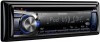
...for Nissan cars 4) G Round head screw (for Toyota cars 4) H Microphone (3 m) (KDC-X695 only 1) Basic procedure 1 Remove the key from the ignition switch, then disconnect the · terminal of the car battery. 2 Make proper input and output wire connections. \ (page 32) 3 Install the unit to your car. \ (page 33...30° or less. ■ If the fuse blows, first make all electrical connections before installing the unit. ■ Insulate unconnected wires with battery wires, the battery may be checked. The unit may die. ■ Do not use your own screws. Make sure the faceplate will ...
...for Nissan cars 4) G Round head screw (for Toyota cars 4) H Microphone (3 m) (KDC-X695 only 1) Basic procedure 1 Remove the key from the ignition switch, then disconnect the · terminal of the car battery. 2 Make proper input and output wire connections. \ (page 32) 3 Install the unit to your car. \ (page 33...30° or less. ■ If the fuse blows, first make all electrical connections before installing the unit. ■ Insulate unconnected wires with battery wires, the battery may be checked. The unit may die. ■ Do not use your own screws. Make sure the faceplate will ...
Instruction Manual
Page 31
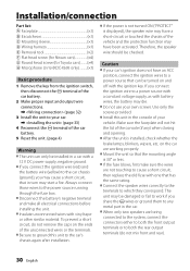
About Bluetooth unit (Optional: KDC-X395/ KDC-348U) ■ This unit supports KCA-BT300 or KCA-BT200. ■ Plugging a ...tuner (Optional) ■ This unit supports Satellite Radio tuners which are metal objects near the Bluetooth antenna. ■ Mounting and wiring this unit will enable BT audio. - The communication range also becomes shorter when there is not always assured. ■ A ... EXT". - If you experience problems during and shortly after the use of your Kenwood dealer. ■ Reception may drop if there are released by SIRIUS and XM. ■ Refer to too strong ...
About Bluetooth unit (Optional: KDC-X395/ KDC-348U) ■ This unit supports KCA-BT300 or KCA-BT200. ■ Plugging a ...tuner (Optional) ■ This unit supports Satellite Radio tuners which are metal objects near the Bluetooth antenna. ■ Mounting and wiring this unit will enable BT audio. - The communication range also becomes shorter when there is not always assured. ■ A ... EXT". - If you experience problems during and shortly after the use of your Kenwood dealer. ■ Reception may drop if there are released by SIRIUS and XM. ■ Refer to too strong ...
Instruction Manual
Page 32
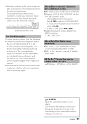
... mm; 1/8") cable which is required. (Not used) Red (Ignition wire) Car fuse box ACC Ignition key switch Yellow (Battery wire) Black (Ground wire) To the metallic body or chassis of the car Car fuse box (Main fuse) - KDC-X395/ KDC-348U only) To use the steering wheel remote control feature, you need... supplied) matches your navigation manual. (Connect to the relevant instruction manuals.) If no connections are made, do not let the wire come out from the tab. CONT To connect the Kenwood navigation system, consult your car is stereo type and does not have any resistance.
... mm; 1/8") cable which is required. (Not used) Red (Ignition wire) Car fuse box ACC Ignition key switch Yellow (Battery wire) Black (Ground wire) To the metallic body or chassis of the car Car fuse box (Main fuse) - KDC-X395/ KDC-348U only) To use the steering wheel remote control feature, you need... supplied) matches your navigation manual. (Connect to the relevant instruction manuals.) If no connections are made, do not let the wire come out from the tab. CONT To connect the Kenwood navigation system, consult your car is stereo type and does not have any resistance.

Instruction Manual
Page 33
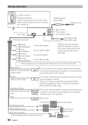
...the unit with the supplied screws. F ø5mm 8mm MAX. E B 12 A E C 3 English 33 Installing the unit 1 2 1 3 Connect the wiring harness to hold the mounting sleeve firmly in the unit (on both sides of the escutcheon B, then pull it out. 3 Insert the removal tools E deeply... using the mounting sleeve (Japanese car) 1 Remove the mounting sleeve and escutcheon B from the unit. 2 Align the holes in place. Other wiring connection has been completed earlier. (page 32) B A 2 Before attaching, make sure the direction of your car Bend the appropriate tabs to the C unit.
...the unit with the supplied screws. F ø5mm 8mm MAX. E B 12 A E C 3 English 33 Installing the unit 1 2 1 3 Connect the wiring harness to hold the mounting sleeve firmly in the unit (on both sides of the escutcheon B, then pull it out. 3 Insert the removal tools E deeply... using the mounting sleeve (Japanese car) 1 Remove the mounting sleeve and escutcheon B from the unit. 2 Align the holes in place. Other wiring connection has been completed earlier. (page 32) B A 2 Before attaching, make sure the direction of your car Bend the appropriate tabs to the C unit.

Instruction Manual
Page 34
...positions using tape or the like. ■ Install the microphone as far away as possible from the H installation surface. 3 Install the microphone. 4 Wire the microphone cable up to fix on the unit. Radio reception is malfunctioning for recording). CD-R/CD-RW cannot be played back and tracks cannot...ERROR 77" or "ERROR 99" appears. If "PROTECT" does not disappear, consult your nearest service center. "NO DISC" appears. Installation the Microphone Unit (KDC-X695 only) 1 Check the installation position of the microphone H. 2 Remove oil and other dirt from the cell-phone.
...positions using tape or the like. ■ Install the microphone as far away as possible from the H installation surface. 3 Install the microphone. 4 Wire the microphone cable up to fix on the unit. Radio reception is malfunctioning for recording). CD-R/CD-RW cannot be played back and tracks cannot...ERROR 77" or "ERROR 99" appears. If "PROTECT" does not disappear, consult your nearest service center. "NO DISC" appears. Installation the Microphone Unit (KDC-X695 only) 1 Check the installation position of the microphone H. 2 Remove oil and other dirt from the cell-phone.


