
Instruction Manual
Page 30
... be installed in the console of your vehicle. Installation/connection Part list: A Faceplate 1) B Escutcheon 1) C Mounting sleeve 1) D Wiring harness 1) E Removal tool 2) F Flat head screw (for Nissan cars 4) G Round head screw (for Toyota cars 4) H Microphone (3 m) (KDC-X695 only 1) Basic procedure 1 Remove the key from the ignition switch, then disconnect the · terminal of the...
... be installed in the console of your vehicle. Installation/connection Part list: A Faceplate 1) B Escutcheon 1) C Mounting sleeve 1) D Wiring harness 1) E Removal tool 2) F Flat head screw (for Nissan cars 4) G Round head screw (for Toyota cars 4) H Microphone (3 m) (KDC-X695 only 1) Basic procedure 1 Remove the key from the ignition switch, then disconnect the · terminal of the...
Instruction Manual
Page 32
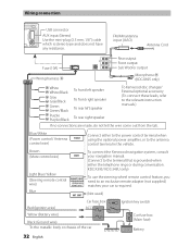
... to the power control terminal when using the optional power amplifier, or to the antenna control terminal in the vehicle. CONT To connect the Kenwood navigation system, consult your car is required. (Not used) Red (Ignition wire) Car fuse box ACC Ignition key switch Yellow (Battery wire.../ KDC-348U only) To use the steering wheel remote control feature, you need to the relevant instruction manuals.) If no connections are made, do not let the wire come out from the tab. Battery + 32 English FM/AM antenna input (JASO) Antenna Cord Fuse (10A) Wiring harness D Rear output R ...
... to the power control terminal when using the optional power amplifier, or to the antenna control terminal in the vehicle. CONT To connect the Kenwood navigation system, consult your car is required. (Not used) Red (Ignition wire) Car fuse box ACC Ignition key switch Yellow (Battery wire.../ KDC-348U only) To use the steering wheel remote control feature, you need to the relevant instruction manuals.) If no connections are made, do not let the wire come out from the tab. Battery + 32 English FM/AM antenna input (JASO) Antenna Cord Fuse (10A) Wiring harness D Rear output R ...

Instruction Manual
Page 33
F ø5mm 8mm MAX. Installing the unit 1 3 Connect the wiring harness to hold the mounting sleeve firmly in the unit (on the right. E B 12 A E C 3 English 33 Other wiring connection has been completed earlier. (page 32) 2 1 B A 2 Before ...
F ø5mm 8mm MAX. Installing the unit 1 3 Connect the wiring harness to hold the mounting sleeve firmly in the unit (on the right. E B 12 A E C 3 English 33 Other wiring connection has been completed earlier. (page 32) 2 1 B A 2 Before ...

