Instruction Manual
Page 1
... read through this instruction manual. KAC-X542 4/3/2 CHANNEL POWER AMPLIFIER 7 page 2-9 INSTRUCTION MANUAL AMPLIFICATEUR DE PUISSANCE 4/3/2 CANAUX 7 page 10-17 MODE D'EMPLOI AMPLIFICADOR DE POTENCIA DE 4/3/2 CANALES 7 página 18-25 MANUAL DE INSTRUCCIONES Take the time to the model and serial numbers whenever you obtain the best performance from your Kenwood dealer for information or service...
... read through this instruction manual. KAC-X542 4/3/2 CHANNEL POWER AMPLIFIER 7 page 2-9 INSTRUCTION MANUAL AMPLIFICATEUR DE PUISSANCE 4/3/2 CANAUX 7 page 10-17 MODE D'EMPLOI AMPLIFICADOR DE POTENCIA DE 4/3/2 CANALES 7 página 18-25 MANUAL DE INSTRUCCIONES Take the time to the model and serial numbers whenever you obtain the best performance from your Kenwood dealer for information or service...
Instruction Manual
Page 2
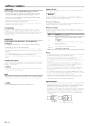
...fuse of greater current-handling capacity than the maximum output power (in Watts) of the unit. • Do not install the unit in the instruction manual. NOTE This Class B digital apparatus complies with a diameter of 8 mm² (AWG 8) or greater.) • When more than the unit's... when the engine is running, connect a line noise filter (optional) to each amplifier. NOTE Turn the power OFF and release the protection. terminal. FCC WARNING This equipment may cause your Kenwood dealer. Protection function There is a Protection function installed in 2004 or later can ...
...fuse of greater current-handling capacity than the maximum output power (in Watts) of the unit. • Do not install the unit in the instruction manual. NOTE This Class B digital apparatus complies with a diameter of 8 mm² (AWG 8) or greater.) • When more than the unit's... when the engine is running, connect a line noise filter (optional) to each amplifier. NOTE Turn the power OFF and release the protection. terminal. FCC WARNING This equipment may cause your Kenwood dealer. Protection function There is a Protection function installed in 2004 or later can ...
Instruction Manual
Page 3
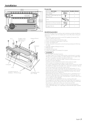
...The installation to the vehicle should securely fasten the unit to select the proper setting and connection. 1. terminal of the units. 4. Install the amplifier in a place where people, resins, and other substances that electrical equipment such as a gasoline tank, brake pipe, or wiring harness, and ...following this unit in a place where the cooling fan and ducts of settings and connections possible according to applications, read the instruction manual well to a place in the below locations; (Unstable location, In a location that interferes with it will not come into contact ...
...The installation to the vehicle should securely fasten the unit to select the proper setting and connection. 1. terminal of the units. 4. Install the amplifier in a place where people, resins, and other substances that electrical equipment such as a gasoline tank, brake pipe, or wiring harness, and ...following this unit in a place where the cooling fan and ducts of settings and connections possible according to applications, read the instruction manual well to a place in the below locations; (Unstable location, In a location that interferes with it will not come into contact ...
Instruction Manual
Page 5
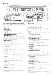
... outputs the band of higher frequencies than the maximum output of systems by combining the switches and functions described in the instruction manual of the center unit connected with the "HPF FREQUENCY" control. • OFF position: The entire bandwidth is "ON", the... to be connected should have an impedance of the OPERATION switch. 1 # Power indicator Lights when the POWER switch is a 4 channel amplifier including 2 stereo amplifiers in a body. When multiple speakers are to be connected, ensure that the quality of the audible frequencies can be improved. ( OPERATION...
... outputs the band of higher frequencies than the maximum output of systems by combining the switches and functions described in the instruction manual of the center unit connected with the "HPF FREQUENCY" control. • OFF position: The entire bandwidth is "ON", the... to be connected should have an impedance of the OPERATION switch. 1 # Power indicator Lights when the POWER switch is a 4 channel amplifier including 2 stereo amplifiers in a body. When multiple speakers are to be connected, ensure that the quality of the audible frequencies can be improved. ( OPERATION...
Instruction Manual
Page 7
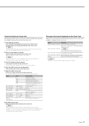
...speaker cord is displayed. Control an Amp from Center Unit The following explains how to control the sound of Amplifier B by operating the Amplifier Control of the unit from the Center Unit. 1 Enter AMP Control mode Select the AMP Control mode by... following the instructions given on the Operation Manual of the Center Unit. 2 Select an amp number to operate Operate the desired set item with the Amp Control, an error status of the amplifier is displayed on the Center Unit. You...When you use the Amp Control in the STANDBY mode, message "AMP OFF" is generated to the Kenwood's dealership.
...speaker cord is displayed. Control an Amp from Center Unit The following explains how to control the sound of Amplifier B by operating the Amplifier Control of the unit from the Center Unit. 1 Enter AMP Control mode Select the AMP Control mode by... following the instructions given on the Operation Manual of the Center Unit. 2 Select an amp number to operate Operate the desired set item with the Amp Control, an error status of the amplifier is displayed on the Center Unit. You...When you use the Amp Control in the STANDBY mode, message "AMP OFF" is generated to the Kenwood's dealership.


