Instruction Manual
Page 1
Familiarity with installation and operation procedures will help you call upon your Kenwood dealer for information or service on the warranty card, and in the space provided below. KAC-X542 4/3/2 CHANNEL POWER AMPLIFIER 7 page 2-9 INSTRUCTION MANUAL AMPLIFICATEUR DE PUISSANCE 4/3/2 CANAUX 7 page 10-17 MODE D'EMPLOI AMPLIFICADOR DE POTENCIA DE 4/3/2 CANALES 7 página 18-25 MANUAL DE...
Familiarity with installation and operation procedures will help you call upon your Kenwood dealer for information or service on the warranty card, and in the space provided below. KAC-X542 4/3/2 CHANNEL POWER AMPLIFIER 7 page 2-9 INSTRUCTION MANUAL AMPLIFICATEUR DE PUISSANCE 4/3/2 CANAUX 7 page 10-17 MODE D'EMPLOI AMPLIFICADOR DE POTENCIA DE 4/3/2 CANALES 7 página 18-25 MANUAL DE...
Instruction Manual
Page 4
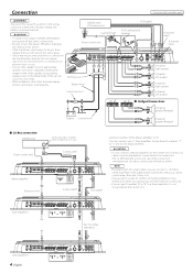
... 23 ID NUMBER TO H/U REMOTE RESET A channel Right speaker A channel Left speaker B channel Right speaker B channel Left speaker ■ Bridged Connections A channel Speaker (Bridged) Battery Ground wire* B channel Speaker (Bridged) ■ LX-Bus connection CENTER UNIT Power control wire 30 30 FUSE(30A×2) POWER IN Master amplifier Extension wire* To Kenwood disc changer/ External optional accessory Control...
... 23 ID NUMBER TO H/U REMOTE RESET A channel Right speaker A channel Left speaker B channel Right speaker B channel Left speaker ■ Bridged Connections A channel Speaker (Bridged) Battery Ground wire* B channel Speaker (Bridged) ■ LX-Bus connection CENTER UNIT Power control wire 30 30 FUSE(30A×2) POWER IN Master amplifier Extension wire* To Kenwood disc changer/ External optional accessory Control...
Instruction Manual
Page 5
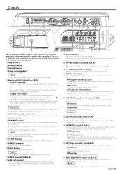
... B. NOTE For the pre-output level, refer to be used . (Make connections to the LEFT channel 9 and the RIGHT channel · SPEAKER OUTPUT terminals.) The speakers to amplifiers when you use it On again. 8 TO H/U terminal After you have set to "LPF". ^ FILTER...(High-Pass Filter) position: The filter outputs the band of the OPERATION switch. 1 # Power indicator Lights when the POWER switch is a 4 channel amplifier including 2 stereo amplifiers in the following. 1 Fuse (30 A × 2) 2 Battery terminal 3 Ground terminal 4 Power control terminal Controls the unit ON/OFF....
... B. NOTE For the pre-output level, refer to be used . (Make connections to the LEFT channel 9 and the RIGHT channel · SPEAKER OUTPUT terminals.) The speakers to amplifiers when you use it On again. 8 TO H/U terminal After you have set to "LPF". ^ FILTER...(High-Pass Filter) position: The filter outputs the band of the OPERATION switch. 1 # Power indicator Lights when the POWER switch is a 4 channel amplifier including 2 stereo amplifiers in the following. 1 Fuse (30 A × 2) 2 Battery terminal 3 Ground terminal 4 Power control terminal Controls the unit ON/OFF....
Instruction Manual
Page 8
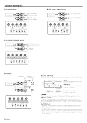
...with the subwoofer. • Ensure that the withstand voltage and current ratings of the capacitors (C) and coils (L) are sufficient. System examples ■ 4-channel system CENTER UNIT LL R AR LL R BR Front Left speaker Front Right speaker Rear Left speaker Rear Right speaker 150 100 70 50 200 LPF...ch FILTER HPF AMP CONT ON A ch ISF OPERATION HPF OPERATION ON MONO(Lch) ON MONO(Lch) OFF LPF OFF OFF STEREO OFF STEREO ■ 2-channel + Subwoofer system CENTER UNIT LL R AR L L R BR Left speaker (High pass) Right speaker (High pass) Subwoofer (Bridged) 150 100 70 ...
...with the subwoofer. • Ensure that the withstand voltage and current ratings of the capacitors (C) and coils (L) are sufficient. System examples ■ 4-channel system CENTER UNIT LL R AR LL R BR Front Left speaker Front Right speaker Rear Left speaker Rear Right speaker 150 100 70 50 200 LPF...ch FILTER HPF AMP CONT ON A ch ISF OPERATION HPF OPERATION ON MONO(Lch) ON MONO(Lch) OFF LPF OFF OFF STEREO OFF STEREO ■ 2-channel + Subwoofer system CENTER UNIT LL R AR L L R BR Left speaker (High pass) Right speaker (High pass) Subwoofer (Bridged) 150 100 70 ...
Instruction Manual
Page 9
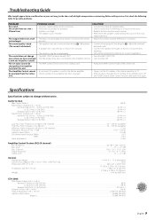
...set improperly. • The AMP CONT has been turned "OFF". • The filtered band has been controlled by the Amplifier Control of the unit. Specifications Specifications subject to change even when you have changed it On again. Audio Section Max Power Output... Hz - 70 kHz Signal to Noise Ratio...105 dB Sensitivity (rated output) (MAX.) ...0.2 V Sensitivity (rated output) (MIN.) ...5.0 V Input Impedance ...10 kΩ Amplifier Control Section (EQ) (B channel) Bass frequency ...60 / 80 / 100 / 200 Hz Bass level ...-15 - +15 dB Bass Q factor...1.00 / 1.25 / 1.50 / 2.00 Treble frequency...
...set improperly. • The AMP CONT has been turned "OFF". • The filtered band has been controlled by the Amplifier Control of the unit. Specifications Specifications subject to change even when you have changed it On again. Audio Section Max Power Output... Hz - 70 kHz Signal to Noise Ratio...105 dB Sensitivity (rated output) (MAX.) ...0.2 V Sensitivity (rated output) (MIN.) ...5.0 V Input Impedance ...10 kΩ Amplifier Control Section (EQ) (B channel) Bass frequency ...60 / 80 / 100 / 200 Hz Bass level ...-15 - +15 dB Bass Q factor...1.00 / 1.25 / 1.50 / 2.00 Treble frequency...
