Instruction Manual
Page 1
... below. Model KAC-X10D Serial number US Residence Only Register Online Register your new power amplifier. Refer to read through this instruction manual. KAC-X10D CLASS D MONO POWER AMPLIFIER 7 page 2-7... INSTRUCTION MANUAL AMPLIFICATEUR MONO CLASSE D 7 page 8-13 MODE D'EMPLOI AMPLIFICADOR DE POTENCIA CLASE D MONOFÓNICO 7 página 14-19 MANUAL DE INSTRUCCIONES Take the time to the model and serial numbers whenever you obtain the best performance from your Kenwood...
... below. Model KAC-X10D Serial number US Residence Only Register Online Register your new power amplifier. Refer to read through this instruction manual. KAC-X10D CLASS D MONO POWER AMPLIFIER 7 page 2-7... INSTRUCTION MANUAL AMPLIFICATEUR MONO CLASSE D 7 page 8-13 MODE D'EMPLOI AMPLIFICADOR DE POTENCIA CLASE D MONOFÓNICO 7 página 14-19 MANUAL DE INSTRUCCIONES Take the time to the model and serial numbers whenever you obtain the best performance from your Kenwood...
Instruction Manual
Page 2
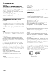
... This equipment may cause your Kenwood dealer. • If the unit does not seem to this unit directly from the speakers when the engine is not installed and used , use a new one power amplifier are expressly approved in a spot exposed to a 12V DC power supply with a negative ground ...connection. • Do not open the top or bottom covers of water splashing. • When replacing a fuse, only use a power supply wiring wire and protective fuse ...
... This equipment may cause your Kenwood dealer. • If the unit does not seem to this unit directly from the speakers when the engine is not installed and used , use a new one power amplifier are expressly approved in a spot exposed to a 12V DC power supply with a negative ground ...connection. • Do not open the top or bottom covers of water splashing. • When replacing a fuse, only use a power supply wiring wire and protective fuse ...
Instruction Manual
Page 3
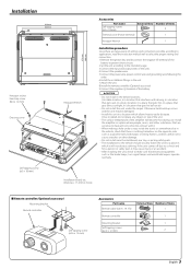
...mm) Accessories Part name Remote cable (6.0 m : 19.7 ft) External View Number of the units. 4.Connect the speaker wires. 5.Connect the power wire, power control wire and grounding wire following this order. 6.Install the installation fittings in the unit. 7.Attach the unit. 8.Install the remote controller. (Optional...circuits. 2.Set the unit according to select the proper setting and connection. 1.Remove the ignition key and disconnect the negative - Install the amplifier in a place where people, resins, and other damage. • Do not install near the dashboard, rear tray, or air bag ...
...mm) Accessories Part name Remote cable (6.0 m : 19.7 ft) External View Number of the units. 4.Connect the speaker wires. 5.Connect the power wire, power control wire and grounding wire following this order. 6.Install the installation fittings in the unit. 7.Attach the unit. 8.Install the remote controller. (Optional...circuits. 2.Set the unit according to select the proper setting and connection. 1.Remove the ignition key and disconnect the negative - Install the amplifier in a place where people, resins, and other damage. • Do not install near the dashboard, rear tray, or air bag ...

Instruction Manual
Page 5
... the left. 40 CENTER UNIT (CD receiver, etc.) Power control wire Master amplifier Extension wire* * Commercially available parts RCA cable* Remote cable Remote controller RCA cable* 40 Slave amplifier 40 Slave amplifier English 5 ■ Multi Amplifier with Remote cable connection (Optional accessory) You can control ...center unit to be connected. 2. Set the LPF frequency and ISF. 3. The volume level of each amplifier is determined by the setting of the Master amplifier (INPUT SENSITIVITY, boost level of the remote controller). Turn the LINE OUT FILTER switch ON. Setting ...
... the left. 40 CENTER UNIT (CD receiver, etc.) Power control wire Master amplifier Extension wire* * Commercially available parts RCA cable* Remote cable Remote controller RCA cable* 40 Slave amplifier 40 Slave amplifier English 5 ■ Multi Amplifier with Remote cable connection (Optional accessory) You can control ...center unit to be connected. 2. Set the LPF frequency and ISF. 3. The volume level of each amplifier is determined by the setting of the Master amplifier (INPUT SENSITIVITY, boost level of the remote controller). Turn the LINE OUT FILTER switch ON. Setting ...
Instruction Manual
Page 6
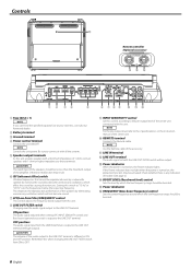
... NOTE If you can't find the specified capacity fuse at your store etc., consult your Kenwood dealer. 2 Battery terminal 3 Ground terminal 4 Power control terminal Controls the unit ON/OFF. NOTE Controls the unit power. NOTE Use the Remote cable of the audio output to the LINE OUT terminal (through... adjusts the frequency band output from the LINE IN terminal is output to the LINE OUT terminal is any indication of the amplifier. Check whether there is different in the instruction manual of the center unit connected with all the systems. 5 Speaker output terminals...
... NOTE If you can't find the specified capacity fuse at your store etc., consult your Kenwood dealer. 2 Battery terminal 3 Ground terminal 4 Power control terminal Controls the unit ON/OFF. NOTE Controls the unit power. NOTE Use the Remote cable of the audio output to the LINE OUT terminal (through... adjusts the frequency band output from the LINE IN terminal is output to the LINE OUT terminal is any indication of the amplifier. Check whether there is different in the instruction manual of the center unit connected with all the systems. 5 Speaker output terminals...


