Instructions
Page 1
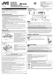
...this symbol should be assured. DON'T remove any other . - DON'T leave equipment switched on 12 V DC, NEGATIVE ground electrical systems. JVC recommends consulting a qualified technician for unattended operation or has a standby mode. DON'T listen to your hearing. Overheating will help prevent... redo the wirings. • Use the speakers with an impedance of this unit, be disposed as this product and the battery, please do this battery contains lead. 1 Notice: Battery The sign Pb below the Model No. LVT2205-001A [K/US] KS-AX3104 KS-AX3102 KS-AX3101D POWER AMPLIFIER...
...this symbol should be assured. DON'T remove any other . - DON'T leave equipment switched on 12 V DC, NEGATIVE ground electrical systems. JVC recommends consulting a qualified technician for unattended operation or has a standby mode. DON'T listen to your hearing. Overheating will help prevent... redo the wirings. • Use the speakers with an impedance of this unit, be disposed as this product and the battery, please do this battery contains lead. 1 Notice: Battery The sign Pb below the Model No. LVT2205-001A [K/US] KS-AX3104 KS-AX3102 KS-AX3101D POWER AMPLIFIER...
Instructions
Page 3
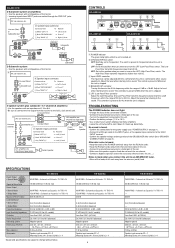
...Hz when the unit is turned on the LPF (Low-Pass Filter) switch. Line out (Front) Å JVC car receiver, etc. *2 JVC amplifier, etc. *2 (Purchased separately) Line out (Center) *2 Subwoofer out Line out (Rear) *2 PRE ...wirings and the position of the car. • Turn on the equipment connected to this position when the unit is preset to this position. Connector lead To Receiver a White "LEFT (+)" = Left (+) lead b Black "RECEIVER GND" = Chassis*1 c Gray "RIGHT (+)" = Right (+) lead PRE OUT INPUT HIGH INPUT L L/MONO R R Subwoofer Subwoofer CONTROLS KS-AX3104...
...Hz when the unit is turned on the LPF (Low-Pass Filter) switch. Line out (Front) Å JVC car receiver, etc. *2 JVC amplifier, etc. *2 (Purchased separately) Line out (Center) *2 Subwoofer out Line out (Rear) *2 PRE ...wirings and the position of the car. • Turn on the equipment connected to this position when the unit is preset to this position. Connector lead To Receiver a White "LEFT (+)" = Left (+) lead b Black "RECEIVER GND" = Chassis*1 c Gray "RIGHT (+)" = Right (+) lead PRE OUT INPUT HIGH INPUT L L/MONO R R Subwoofer Subwoofer CONTROLS KS-AX3104...