
Technical Product Specification for Intel Desktop Board DN2800MT
Page 3
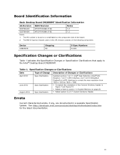
... Desktop Board DN2800MT Identification Information AA Revision BIOS Revision Notes G23738-600 MTCDT10N.86A.0146 1,2 G23738-800 MTCDT10N.86A.0152 1,2 Notes: 1. Table 1. iii The NM10 Express Chipset used on the component side of the board. 2. See http://developer.intel.com/products... Update. The AA number is found on a small label on this AA revision consists of the following component: Device CG82NM10 Stepping B0 S-Spec Numbers SLGXX Specification Changes or Clarifications Table 1 indicates the Specification Changes or Specification Clarifications that apply to 1920 x...
... Desktop Board DN2800MT Identification Information AA Revision BIOS Revision Notes G23738-600 MTCDT10N.86A.0146 1,2 G23738-800 MTCDT10N.86A.0152 1,2 Notes: 1. Table 1. iii The NM10 Express Chipset used on the component side of the board. 2. See http://developer.intel.com/products... Update. The AA number is found on a small label on this AA revision consists of the following component: Device CG82NM10 Stepping B0 S-Spec Numbers SLGXX Specification Changes or Clarifications Table 1 indicates the Specification Changes or Specification Clarifications that apply to 1920 x...

Technical Product Specification for Intel Desktop Board DN2800MT
Page 26
...Interface Type: allows the system integrator to select whether the eDP panel is disabled (and all parameters hidden) by default. 2. Intel Desktop Board DN2800MT Technical Product Specification In addition, BIOS setup provides the following : 1. Internal flat panel display connectivity is a 1-lane, 2-lane...favor of the LVDS configuration to avoid end users potentially rendering the display unusable. • Brightness Steps: allows the system integrator to configure the brightness steps for the operating system's "screen brightness" control (such as the "Screen brightness" adjustment slider ...
...Interface Type: allows the system integrator to select whether the eDP panel is disabled (and all parameters hidden) by default. 2. Intel Desktop Board DN2800MT Technical Product Specification In addition, BIOS setup provides the following : 1. Internal flat panel display connectivity is a 1-lane, 2-lane...favor of the LVDS configuration to avoid end users potentially rendering the display unusable. • Brightness Steps: allows the system integrator to configure the brightness steps for the operating system's "screen brightness" control (such as the "Screen brightness" adjustment slider ...
Product Guide for Intel Desktop Board DN2800MT
Page 15
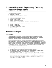
...computer from its power source and from any telecommunications links, networks, or modems before you begin: • Always follow the steps in each procedure in this chapter assume familiarity with the general terminology associated with personal computers and with the safety practices and ... a processor • Install and remove system memory • Connect to SATA drives • Install a PCI Express Mini Card • Install an Intel Z-U130 USB Solid-State Drive or Compatible Device • Connect to the internal headers and connectors • Connect a system fan • Connect a...
...computer from its power source and from any telecommunications links, networks, or modems before you begin: • Always follow the steps in each procedure in this chapter assume familiarity with the general terminology associated with personal computers and with the safety practices and ... a processor • Install and remove system memory • Connect to SATA drives • Install a PCI Express Mini Card • Install an Intel Z-U130 USB Solid-State Drive or Compatible Device • Connect to the internal headers and connectors • Connect a system fan • Connect a...
Product Guide for Intel Desktop Board DN2800MT
Page 19
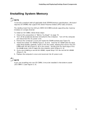
...in the bottom socket (SO-DIMM 1) (see Figure 5). 4. Turn off the computer and disconnect the AC power cord. 3. Turn off all applicable Intel SDRAM memory specifications, the board requires SO-DIMMs that support the Serial Presence Detect (SPD) data structure. Remove the computer's cover and locate the ... the back edge of the SO-DIMM down until it into the retention arms (Figure 5, C). 5. If you are installing a second SO-DIMM, repeat Step 4 for the second SO-DIMM (Figure 5, D). 6. Hold the SO-DIMM with the back edge tilted slightly upwards, insert it snaps into the socket,...
...in the bottom socket (SO-DIMM 1) (see Figure 5). 4. Turn off the computer and disconnect the AC power cord. 3. Turn off all applicable Intel SDRAM memory specifications, the board requires SO-DIMMs that support the Serial Presence Detect (SPD) data structure. Remove the computer's cover and locate the ... the back edge of the SO-DIMM down until it into the retention arms (Figure 5, C). 5. If you are installing a second SO-DIMM, repeat Step 4 for the second SO-DIMM (Figure 5, D). 6. Hold the SO-DIMM with the back edge tilted slightly upwards, insert it snaps into the socket,...

Product Guide for Intel Desktop Board DN2800MT
Page 24
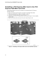
... Express Full-/Half-Mini Card slot (Figure 1, AA). 3. To install a PCI Express Half-Mini Card in this slot, see Figure 8 and follow these steps: 1. Locate the PCI Express Full-/Half-Mini Card slot (Figure 1, AA). 3. Observe the precautions in Figure 8, C. 4. Align the mounting holes and ...secure the card in the Desktop Board's PCI Express Full-/Half-Mini Card slot. Intel Desktop Board DN2800MT Product Guide Installing a PCI Express Mini Card in the PCI Express Full-/Half-Mini Card Slot A PCI Express Full-Mini or Half-Mini ...
... Express Full-/Half-Mini Card slot (Figure 1, AA). 3. To install a PCI Express Half-Mini Card in this slot, see Figure 8 and follow these steps: 1. Locate the PCI Express Full-/Half-Mini Card slot (Figure 1, AA). 3. Observe the precautions in Figure 8, C. 4. Align the mounting holes and ...secure the card in the Desktop Board's PCI Express Full-/Half-Mini Card slot. Intel Desktop Board DN2800MT Product Guide Installing a PCI Express Mini Card in the PCI Express Full-/Half-Mini Card Slot A PCI Express Full-Mini or Half-Mini ...
Product Guide for Intel Desktop Board DN2800MT
Page 26
... and secure the card in this slot, see Figure 9 and follow these steps: 1. To install a PCI Express card in place (Figure 9, B). Installing a PCI Express Mini Card in the Desktop Board's PCI Express Half-Mini Card slot. Figure 9. Intel Desktop Board DN2800MT Product Guide Installing a PCI Express Mini Card in the PCI Express Half...
... and secure the card in this slot, see Figure 9 and follow these steps: 1. To install a PCI Express card in place (Figure 9, B). Installing a PCI Express Mini Card in the Desktop Board's PCI Express Half-Mini Card slot. Figure 9. Intel Desktop Board DN2800MT Product Guide Installing a PCI Express Mini Card in the PCI Express Half...
Product Guide for Intel Desktop Board DN2800MT
Page 27
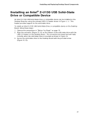
..., B). 27 Secure the solid state drive to the Desktop Board with the USB 2.0 header on the Desktop Board, follow these steps: 1. To install an Intel Z-U130 USB Solid-State Drive or compatible device on the Desktop Board. The connectors are keyed and will mate correctly when the solid... shown in Figure 10. 3. This header provides support for the solid-state drive. Installing and Replacing Desktop Board Components Installing an Intel® Z-U130 USB Solid-State Drive or Compatible Device An Intel Z-U130 USB Solid-State Drive or compatible device can be installed on page 15. 2.
..., B). 27 Secure the solid state drive to the Desktop Board with the USB 2.0 header on the Desktop Board, follow these steps: 1. To install an Intel Z-U130 USB Solid-State Drive or compatible device on the Desktop Board. The connectors are keyed and will mate correctly when the solid... shown in Figure 10. 3. This header provides support for the solid-state drive. Installing and Replacing Desktop Board Components Installing an Intel® Z-U130 USB Solid-State Drive or Compatible Device An Intel Z-U130 USB Solid-State Drive or compatible device can be installed on page 15. 2.
Product Guide for Intel Desktop Board DN2800MT
Page 43
..., A). 6. Disconnect the computer's power cord from the board. Replace the computer cover. 43 Installing and Replacing Desktop Board Components To replace the battery, follow these steps: 1. It is attached to the computer. Remove the computer cover. 4. Disconnect the battery cable from the adhesive pad on the board (see page 15). 2. Turn...
..., A). 6. Disconnect the computer's power cord from the board. Replace the computer cover. 43 Installing and Replacing Desktop Board Components To replace the battery, follow these steps: 1. It is attached to the computer. Remove the computer cover. 4. Disconnect the battery cable from the adhesive pad on the board (see page 15). 2. Turn...

Product Guide for Intel Desktop Board DN2800MT
Page 45
... to a removable USB device. This step is required. You can access the BIOS Setup program by either using the Intel Express BIOS Update utility or the Intel® Flash Memory Update Utility, and how to the DN2800MT page. To update the BIOS with the Intel® Express BIOS Update Utility With... the Intel Express BIOS Update utility you are updating the ...
... to a removable USB device. This step is required. You can access the BIOS Setup program by either using the Intel Express BIOS Update utility or the Intel® Flash Memory Update Utility, and how to the DN2800MT page. To update the BIOS with the Intel® Express BIOS Update Utility With... the Intel Express BIOS Update utility you are updating the ...