

Owners Manual
Page 3
...turning on clothing, change clothing immediately. • Never overfill fuel tank. Always place containers on the ground away from your view of children. Replace gas cap and tighten securely. Allow machine to stop . Stop machine if anyone enters the area. • Never carry passengers. • ...the watchful care of ignition. • Use only approved gasoline container. • Never remove gas cap or add fuel with manufacturer's recommended parts, when necessary. • Mower blades are sharp. If the tires lose traction, disengage the blades and proceed slowly straight down the slope....
...turning on clothing, change clothing immediately. • Never overfill fuel tank. Always place containers on the ground away from your view of children. Replace gas cap and tighten securely. Allow machine to stop . Stop machine if anyone enters the area. • Never carry passengers. • ...the watchful care of ignition. • Use only approved gasoline container. • Never remove gas cap or add fuel with manufacturer's recommended parts, when necessary. • Mower blades are sharp. If the tires lose traction, disengage the blades and proceed slowly straight down the slope....
Owners Manual
Page 5
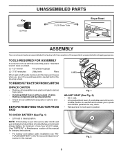
...Standard wrench sizes are in seat. • Lift up adjustment lever (A) and slide seat until a com- A Fig. 2 5 Key (2) Keys UNASSEMBLED PARTS (1) Oil Drain Tube Slope Sheet ASSEMBLY Your new tractor has been assembled at 6-10 amps. (See "BATTERY" in Maintenance section of carton. fortable position .... Remove end panels and lay side panels flat. • Check for charging instructions). • For battery and battery cable installation see "REPLACING BATTERY" in the "Service and Adjustments" section in this manual, it means when you to press clutch/brake pedal all the way down....
...Standard wrench sizes are in seat. • Lift up adjustment lever (A) and slide seat until a com- A Fig. 2 5 Key (2) Keys UNASSEMBLED PARTS (1) Oil Drain Tube Slope Sheet ASSEMBLY Your new tractor has been assembled at 6-10 amps. (See "BATTERY" in Maintenance section of carton. fortable position .... Remove end panels and lay side panels flat. • Check for charging instructions). • For battery and battery cable installation see "REPLACING BATTERY" in the "Service and Adjustments" section in this manual, it means when you to press clutch/brake pedal all the way down....

Owners Manual
Page 6
... driving tractor, be properly leveled. PLEASE REVIEW THE FOLLOWING CHECKLIST: ✓ All assembly instructions have been completed. ✓ No remaining loose parts in the Operation section of this manual). ✓ It is in disengaged position to PSI shown on your tractor for shipping purposes. Operate ...Be sure brake system is properly leveled side-to-side/ front-to-rear for best cutting results. (Tires must be properly inflated for replacing motion and mower blade drive belts in the Operation section of this manual). 6 WHILE LEARNING HOW TO USE YOUR TRACTOR, PAY EXTRA ...
... driving tractor, be properly leveled. PLEASE REVIEW THE FOLLOWING CHECKLIST: ✓ All assembly instructions have been completed. ✓ No remaining loose parts in the Operation section of this manual). ✓ It is in disengaged position to PSI shown on your tractor for shipping purposes. Operate ...Be sure brake system is properly leveled side-to-side/ front-to-rear for best cutting results. (Tires must be properly inflated for replacing motion and mower blade drive belts in the Operation section of this manual). 6 WHILE LEARNING HOW TO USE YOUR TRACTOR, PAY EXTRA ...

Owners Manual
Page 15
... without first setting the parking brake should never operate unless the operator is hazardous, could damage your tractor and void your local parts dealer. If your tractor. MANDREL ASSEMBLY BLADE • The engine should not start unless the brake pedal is fully depressed,... the engine is sufficient for proper PSI). • Keep tires free of the battery with grease or petroleum jelly. • Reinstall battery (See "REPLACING BATTERY" in the engine "ON" position and the attachment clutch engaged, any maintenance. ROS "ON" POSITION 02828 ENGINE "ON" POSITION (NORMAL OPERATING...
... without first setting the parking brake should never operate unless the operator is hazardous, could damage your tractor and void your local parts dealer. If your tractor. MANDREL ASSEMBLY BLADE • The engine should not start unless the brake pedal is fully depressed,... the engine is sufficient for proper PSI). • Keep tires free of the battery with grease or petroleum jelly. • Reinstall battery (See "REPLACING BATTERY" in the engine "ON" position and the attachment clutch engaged, any maintenance. ROS "ON" POSITION 02828 ENGINE "ON" POSITION (NORMAL OPERATING...
Owners Manual
Page 17
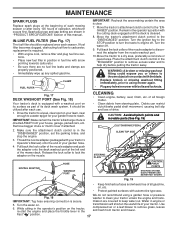
...cleaned. 8. WARNING: A broken or missing washout fitting could expose you or others to thrown objects from contact with the blade. • Replace broken or missing washout fitting immediately, prior to the "ENGAGED" position. Make sure the attachment clutch control is secure. Water in "PRODUCT SPECIFICATIONS...steering plate. Release the lock collar to clean your garden hose to keep water out. CAUTION: Avoid all pinch points and movable parts (See Fig. 19) CLUTCH/BRAKE PEDAL CLEAN TOP SIDE STEERING PLATE NOZZLE ADAPTER HOSE WASHOUT PORT CAUTION: PINCH POINTS STEERING SYSTEM, ...
...cleaned. 8. WARNING: A broken or missing washout fitting could expose you or others to thrown objects from contact with the blade. • Replace broken or missing washout fitting immediately, prior to the "ENGAGED" position. Make sure the attachment clutch control is secure. Water in "PRODUCT SPECIFICATIONS...steering plate. Release the lock collar to clean your garden hose to keep water out. CAUTION: Avoid all pinch points and movable parts (See Fig. 19) CLUTCH/BRAKE PEDAL CLEAN TOP SIDE STEERING PLATE NOZZLE ADAPTER HOSE WASHOUT PORT CAUTION: PINCH POINTS STEERING SYSTEM, ...

Owners Manual
Page 22
... Tighten securely. • Connect BLACK grounding cable to allow wheel removal (rear wheel contains a square key - If your local parts dealer. SERVICE AND ADJUSTMENTS FRONT WHEEL TOE-IN/CAMBER Your new tractor front wheel toe-in the MAINTENANCE section of this procedure: ...TERMINAL COVER POSITIVE (RED) CABLE Fig. 34 NEGATIVE (BLACK) CABLE If "jumper cables" are not adjustable. Insert square key. • Replace washers and snap retaining ring securely in or camber, contact a qualified service center. WARNING: Lead-acid batteries generate explosive gases. TO ATTACH JUMPER...
... Tighten securely. • Connect BLACK grounding cable to allow wheel removal (rear wheel contains a square key - If your local parts dealer. SERVICE AND ADJUSTMENTS FRONT WHEEL TOE-IN/CAMBER Your new tractor front wheel toe-in the MAINTENANCE section of this procedure: ...TERMINAL COVER POSITIVE (RED) CABLE Fig. 34 NEGATIVE (BLACK) CABLE If "jumper cables" are not adjustable. Insert square key. • Replace washers and snap retaining ring securely in or camber, contact a qualified service center. WARNING: Lead-acid batteries generate explosive gases. TO ATTACH JUMPER...

Owners Manual
Page 23
... 35) • Raise hood. • Unsnap headlight wire connector. • Stand in the Repair Parts section. TRANSMISSION REMOVAL/REPLACEMENT Should your tractor to an authorized service center for service or replacement, it from starting. • Check wiring. Grasp hood at the factory and adjustment should not be ... to suspected carburetor problems, take your tractor to run poorly, stop running, or prevent it should not be necessary. TO REPLACE FUSE Replace with 20 amp automotive-type plug-in fuse. TO ADJUST CHOKE CONTROL The choke control has been preset at the factory and...
... 35) • Raise hood. • Unsnap headlight wire connector. • Stand in the Repair Parts section. TRANSMISSION REMOVAL/REPLACEMENT Should your tractor to an authorized service center for service or replacement, it from starting. • Check wiring. Grasp hood at the factory and adjustment should not be ... to suspected carburetor problems, take your tractor to run poorly, stop running, or prevent it should not be necessary. TO REPLACE FUSE Replace with 20 amp automotive-type plug-in fuse. TO ADJUST CHOKE CONTROL The choke control has been preset at the factory and...

Owners Manual
Page 24
... of time in minimizing the formation of this manual). Do not empty the gas tank and carburetor if using fuel stabilizer. Inspect moving parts for 30 days or more. NOTE: Fuel stabilizer is an acceptable alternative in storage, battery may require recharging. • To help ...power leakage during storage. placement instructions in the Service and Adjustments section of this manual. • Be sure that does not retain moisture. Replace if necessary. • Touch up all dirt, grease, leaves, etc. Add stabilizer to cool before painting. Always follow the mix ratio...
... of time in minimizing the formation of this manual). Do not empty the gas tank and carburetor if using fuel stabilizer. Inspect moving parts for 30 days or more. NOTE: Fuel stabilizer is an acceptable alternative in storage, battery may require recharging. • To help ...power leakage during storage. placement instructions in the Service and Adjustments section of this manual. • Be sure that does not retain moisture. Replace if necessary. • Touch up all dirt, grease, leaves, etc. Add stabilizer to cool before painting. Always follow the mix ratio...

Owners Manual
Page 25
.... 9. Dirty fuel filter. 5. Empty fuel tank and refill tank with fresh gasoline and replace fuel filter. 8. Blown fuse. 5. Corroded battery terminals. 3. Clean/replace muffler. 13. Loose or damaged wiring. 13. Replace blade. Replace spark plug. 5. Replace fuse. 5. Disengage attachment clutch. 3. Loose/damaged part(s). 1. Faulty solenoid or starter. 9. Engine clicks but will not turn over 1. Engine not...
.... 9. Dirty fuel filter. 5. Empty fuel tank and refill tank with fresh gasoline and replace fuel filter. 8. Blown fuse. 5. Corroded battery terminals. 3. Clean/replace muffler. 13. Loose or damaged wiring. 13. Replace blade. Replace spark plug. 5. Replace fuse. 5. Disengage attachment clutch. 3. Loose/damaged part(s). 1. Faulty solenoid or starter. 9. Engine clicks but will not turn over 1. Engine not...

Owners Manual
Page 26
... listed in parts manual. 11. Check wiring, switches and connections. Buildup of mower housing. 8. Worn/damaged mower drive belt. 3. Replace blade. Travel speed too fast. 2. Shift to ROS "ON" position. Allow grass to dry before stopping engine. 1. Replace blade. Mower...rotate 1. Faulty alternator. 1. See "CLEANING" in "engaged" position. 2. See "TO REMOVE WHEEL" in transmission during shipment or servicing. 5. Replace blade mandrel. Turn switch "ON". 2. uneven Mower blades will not charge 1. Poor grass discharge Headlight(s) not working (if so equipped) 1. ...
... listed in parts manual. 11. Check wiring, switches and connections. Buildup of mower housing. 8. Worn/damaged mower drive belt. 3. Replace blade. Travel speed too fast. 2. Shift to ROS "ON" position. Allow grass to dry before stopping engine. 1. Replace blade. Mower...rotate 1. Faulty alternator. 1. See "CLEANING" in "engaged" position. 2. See "TO REMOVE WHEEL" in transmission during shipment or servicing. 5. Replace blade mandrel. Turn switch "ON". 2. uneven Mower blades will not charge 1. Poor grass discharge Headlight(s) not working (if so equipped) 1. ...

Owners Manual
Page 35
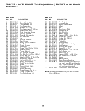
... Cartrdg. inches 1 inch = 25.4 mm For engine service and replacement parts, call the toll free number for your engine manufacturer listed below: Kohler Co. 1-800-544-2444 35 MODEL NUMBER YTH21K46 (96045002901), PRODUCT NO. 960 45 00-29 ENGINE KEY NO. 1 PART NO. 2 532 18 86-55 9 532 19 43-20 12... 532 41 41-18 111 532 41 41-19 113 532 41 41-27 DESCRIPTION Engine Kohler Model No. TRACTOR - - SV610-3212 (430089)(Order parts from engine manufacturer) Muffler Keeper Belt Engine Pulley Engine Tank Fuel Cap Asm Control Throttle Screw # 10 x 0.750 Fuel Line Spark Arrester Kit Clamp...
... Cartrdg. inches 1 inch = 25.4 mm For engine service and replacement parts, call the toll free number for your engine manufacturer listed below: Kohler Co. 1-800-544-2444 35 MODEL NUMBER YTH21K46 (96045002901), PRODUCT NO. 960 45 00-29 ENGINE KEY NO. 1 PART NO. 2 532 18 86-55 9 532 19 43-20 12... 532 41 41-18 111 532 41 41-19 113 532 41 41-27 DESCRIPTION Engine Kohler Model No. TRACTOR - - SV610-3212 (430089)(Order parts from engine manufacturer) Muffler Keeper Belt Engine Pulley Engine Tank Fuel Cap Asm Control Throttle Screw # 10 x 0.750 Fuel Line Spark Arrester Kit Clamp...
Owners Manual
Page 39
...1 59 532 14 10-43 Guard, Tuv Idler (94) 60 532 19 94-71 Arm Brake Mower LH KEY PART NO. RH Keeper Belt Pulley Idler Spring Return Cable Clutch Manual w/Spr. NO. Stud Fastener Nut Lock Hex Flange ...Screw 3/8-16 x 3/4 Washer 13/32 x 13/16 x 12 Ga. pulley/nut/washer and blade bolt/washers not included) Replacement Mower, Complete NOTE: All component dimensions given in U.S. Keeper Belt Eng. Bolt 3/8-16 unc x 2-1/4 Gr. 5 Screw Washout ...Screw 5/16-18 Bolt, Shoulder Wheel, Gauge Washer 13/32 x 1-1/4 x 12 Ga. MODEL NUMBER YTH21K46 (96045002901), PRODUCT NO. 960 45 00-29 MOWER DECK KEY...
...1 59 532 14 10-43 Guard, Tuv Idler (94) 60 532 19 94-71 Arm Brake Mower LH KEY PART NO. RH Keeper Belt Pulley Idler Spring Return Cable Clutch Manual w/Spr. NO. Stud Fastener Nut Lock Hex Flange ...Screw 3/8-16 x 3/4 Washer 13/32 x 13/16 x 12 Ga. pulley/nut/washer and blade bolt/washers not included) Replacement Mower, Complete NOTE: All component dimensions given in U.S. Keeper Belt Eng. Bolt 3/8-16 unc x 2-1/4 Gr. 5 Screw Washout ...Screw 5/16-18 Bolt, Shoulder Wheel, Gauge Washer 13/32 x 1-1/4 x 12 Ga. MODEL NUMBER YTH21K46 (96045002901), PRODUCT NO. 960 45 00-29 MOWER DECK KEY...
Owners Manual
Page 42
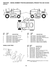
TRACTOR - - MODEL NUMBER YTH21K46 (96045002901), PRODUCT NO. 960 45 00-29 DECALS 47 2 56 2 8 3 1 9 10 KEY NO. 1 2 3 4 5 6 7 8 12 PART NO. PART NO. Tube) NOTE: All component dimensions given in U.S. Decal, Fender WHEELS AND TIRES 1 2 11 3 4 7 10 6 5 9 8 wheel_art_1-tex KEY NO. 9 10 12 - - - - - - inches 1 inch = 25.4 mm ..., Battery Dnge/Poi Decal, Mower Warning Decal, Mower V-Belt Schematic Decal, Bypass Pad, Footrest, LH Pad, Footrest, RH Manual, Owner's (English) Manual, Owner's (Spanish) KEY PART NO. Decal, Replacement Decal, Label Emiss.
TRACTOR - - MODEL NUMBER YTH21K46 (96045002901), PRODUCT NO. 960 45 00-29 DECALS 47 2 56 2 8 3 1 9 10 KEY NO. 1 2 3 4 5 6 7 8 12 PART NO. PART NO. Tube) NOTE: All component dimensions given in U.S. Decal, Fender WHEELS AND TIRES 1 2 11 3 4 7 10 6 5 9 8 wheel_art_1-tex KEY NO. 9 10 12 - - - - - - inches 1 inch = 25.4 mm ..., Battery Dnge/Poi Decal, Mower Warning Decal, Mower V-Belt Schematic Decal, Bypass Pad, Footrest, LH Pad, Footrest, RH Manual, Owner's (English) Manual, Owner's (Spanish) KEY PART NO. Decal, Replacement Decal, Label Emiss.

Parts List
Page 10
... 3/8-16 x 1 Tube Exhaust Washer 9/32 x 7/8 x 16 Ga. inches 1 inch = 25.4 mm For engine service and replacement parts, call the toll free number for your engine manufacturer listed below: Kohler Co. 1-800-544-2444 35 MODEL NUMBER YTH21K46 (96045002601), PRODUCT NO. 960 45 00-26 ENGINE KEY NO. 1 2 9 12 15 18 20 21 28... 29 37 42 45 69 79 81 82 85 87 90 92 94 96 97 138 PART NO. 532 43 83-24 532 18 86-55...
... 3/8-16 x 1 Tube Exhaust Washer 9/32 x 7/8 x 16 Ga. inches 1 inch = 25.4 mm For engine service and replacement parts, call the toll free number for your engine manufacturer listed below: Kohler Co. 1-800-544-2444 35 MODEL NUMBER YTH21K46 (96045002601), PRODUCT NO. 960 45 00-26 ENGINE KEY NO. 1 2 9 12 15 18 20 21 28... 29 37 42 45 69 79 81 82 85 87 90 92 94 96 97 138 PART NO. 532 43 83-24 532 18 86-55...

Parts List
Page 14
... 2-1/4 Gr. 5 Screw Washout Port Quick Connect Coupling Mandrel Assembly (Includes housing, shaft assembly, and bearing only - MODEL NUMBER YTH21K46 (96045002601), PRODUCT NO. 960 45 00-26 MOWER DECK KEY PART NO. NO. NO. DESCRIPTION 63 532 19 94-77 64 532 40 51-38 67 532 40 30-12 68...Belt Bolt Clutch Asm. Baffle Center Front Baffle Front RH Washer 13/32 x 1 x 1/2 11 Ga. pulley/nut/washer and blade bolt/washers not included) Replacement Mower, Complete NOTE: All component dimensions given in U.S. Keeper Belt Eng. Stud Fastener Nut Lock Hex Flange Screw 3/8-16 x 3/4 Washer 13/32 x 13/16...
... 2-1/4 Gr. 5 Screw Washout Port Quick Connect Coupling Mandrel Assembly (Includes housing, shaft assembly, and bearing only - MODEL NUMBER YTH21K46 (96045002601), PRODUCT NO. 960 45 00-26 MOWER DECK KEY PART NO. NO. NO. DESCRIPTION 63 532 19 94-77 64 532 40 51-38 67 532 40 30-12 68...Belt Bolt Clutch Asm. Baffle Center Front Baffle Front RH Washer 13/32 x 1 x 1/2 11 Ga. pulley/nut/washer and blade bolt/washers not included) Replacement Mower, Complete NOTE: All component dimensions given in U.S. Keeper Belt Eng. Stud Fastener Nut Lock Hex Flange Screw 3/8-16 x 3/4 Washer 13/32 x 13/16...

Parts List
Page 17
TRACTOR - - MODEL NUMBER YTH21K46 (96045002601), PRODUCT NO. 960 45 00-26 DECALS 2 56 2 8 9 3 1 4 12 KEY NO. 1 2 3 4 5 6 8 PART NO. PART NO. Tube) NOTE: All component dimensions given in U.S. PART NO. inches 1 inch = 25.4 mm 42 Decal, Replacement Decal, Fender WHEELS AND TIRES 1 2 11 3 4 7 10 5 9 6 8 wheel_art_1-tex KEY NO. 9 12 - - - - - - DESCRIPTION 532 41 91-38 532 42 91...
TRACTOR - - MODEL NUMBER YTH21K46 (96045002601), PRODUCT NO. 960 45 00-26 DECALS 2 56 2 8 9 3 1 4 12 KEY NO. 1 2 3 4 5 6 8 PART NO. PART NO. Tube) NOTE: All component dimensions given in U.S. PART NO. inches 1 inch = 25.4 mm 42 Decal, Replacement Decal, Fender WHEELS AND TIRES 1 2 11 3 4 7 10 5 9 6 8 wheel_art_1-tex KEY NO. 9 12 - - - - - - DESCRIPTION 532 41 91-38 532 42 91...


