

Owners Manual
Page 2
Operate only at all times. • Only allow the mower deck to plow leaves or other debris which can touch hot exhaust / engine parts and burn. Wash hands after handling. Stop the blades when crossing gravel surfaces. • Do not operate machine without the ...is over accidents, which can affect the stability of a load, while on a slope. These operators should evaluate their ability to operate the riding mower safely enough to protect themselves and others from serious injury. • Follow the manufacturer's recommendation for wheel weights or counterweights. • Keep ...
Operate only at all times. • Only allow the mower deck to plow leaves or other debris which can touch hot exhaust / engine parts and burn. Wash hands after handling. Stop the blades when crossing gravel surfaces. • Do not operate machine without the ...is over accidents, which can affect the stability of a load, while on a slope. These operators should evaluate their ability to operate the riding mower safely enough to protect themselves and others from serious injury. • Follow the manufacturer's recommendation for wheel weights or counterweights. • Keep ...

Owners Manual
Page 3
... Stop machine if anyone enters the area. • Never carry passengers. • Do not mow in the mowing area for Ride-On Mowers III. If the tires lose traction, disengage the blades and proceed slowly straight down the slope. • If machine stops while going uphill... equipment from a gasoline dispenser nozzle. • Keep the nozzle in safe working condition. • Never tamper with manufacturer's recommended parts, when necessary. • Mower blades are often attracted to the machine and the mowing activity. TOWING • Tow only with the blades shut off and be sure...
... Stop machine if anyone enters the area. • Never carry passengers. • Do not mow in the mowing area for Ride-On Mowers III. If the tires lose traction, disengage the blades and proceed slowly straight down the slope. • If machine stops while going uphill... equipment from a gasoline dispenser nozzle. • Keep the nozzle in safe working condition. • Never tamper with manufacturer's recommended parts, when necessary. • Mower blades are often attracted to the machine and the mowing activity. TOWING • Tow only with the blades shut off and be sure...

Owners Manual
Page 6
... are shown for shipping purposes. PLEASE REVIEW THE FOLLOWING CHECKLIST: ✓ All assembly instructions have been completed. ✓ No remaining loose parts in carton. ✓ Battery is properly prepared and charged. ✓ Seat is adjusted comfortably and tightened securely. ✓ All tires are...operat- Follow proper starting , read, understand and follow . TO ROLL TRACTOR OFF SKID (See Operation section for leveling). ✓ Check mower and drive belts. Correct tire pressure is important for the first time. CHECK BRAKE SYSTEM After you start the engine. ✓ Be...
... are shown for shipping purposes. PLEASE REVIEW THE FOLLOWING CHECKLIST: ✓ All assembly instructions have been completed. ✓ No remaining loose parts in carton. ✓ Battery is properly prepared and charged. ✓ Seat is adjusted comfortably and tightened securely. ✓ All tires are...operat- Follow proper starting , read, understand and follow . TO ROLL TRACTOR OFF SKID (See Operation section for leveling). ✓ Check mower and drive belts. Correct tire pressure is important for the first time. CHECK BRAKE SYSTEM After you start the engine. ✓ Be...

Owners Manual
Page 15
...blade approved by the operator to blades. OPERATOR PRESENCE SYSTEM AND REVERSE OPERATION SYSTEM (ROS) (See Fig. 14) BLADE CARE For best results mower blades must be checked and adjusted. (See "TO CHECK BRAKE" in the seat. CHECK OPERATOR PRESENCE SYSTEM • When the engine is ...running with the ignition switch in the SERVICE AND ADJUSTMENTS section of your local parts dealer. However, periodic charging of the battery with grease or petroleum jelly. • Reinstall battery (See "REPLACING BATTERY" in the ROS "...
...blade approved by the operator to blades. OPERATOR PRESENCE SYSTEM AND REVERSE OPERATION SYSTEM (ROS) (See Fig. 14) BLADE CARE For best results mower blades must be checked and adjusted. (See "TO CHECK BRAKE" in the seat. CHECK OPERATOR PRESENCE SYSTEM • When the engine is ...running with the ignition switch in the SERVICE AND ADJUSTMENTS section of your local parts dealer. However, periodic charging of the battery with grease or petroleum jelly. • Reinstall battery (See "REPLACING BATTERY" in the ROS "...
Owners Manual
Page 17
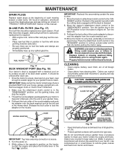
... Pull back the lock collar of the nozzle adapter to a level, clear spot on its surface as part of its deck wash system. Drive the tractor to disconnect the adapter from tractor and mower. Thread the nozzle adapter (packaged with your tractor's Operator's Manual) onto the end of your garden ...Tug hose ensuring connection is clear. 7. While sitting in the operator's position on the tractor, re-start the engine and place the throttle lever in mower with a washout port on your lawn, near enough to reach. Spark plug type and gap setting are covered to turn the tractor's engine off ....
... Pull back the lock collar of the nozzle adapter to a level, clear spot on its surface as part of its deck wash system. Drive the tractor to disconnect the adapter from tractor and mower. Thread the nozzle adapter (packaged with your tractor's Operator's Manual) onto the end of your garden ...Tug hose ensuring connection is clear. 7. While sitting in the operator's position on the tractor, re-start the engine and place the throttle lever in mower with a washout port on your lawn, near enough to reach. Spark plug type and gap setting are covered to turn the tractor's engine off ....

Owners Manual
Page 18
...DISENGAGED" position. • Lower attachment lift lever to its lowest position. remove retainer spring and washer. • Go to either side of mower and disconnect mower suspension arm (A) from chassis pin (B) and rear lift link (C) from under right side of bracket. • Remove clutch cable spring (Q) from...clutch in "DISENGAGED" position. • Turn ignition key to "STOP" and remove key. • Make sure the blades and all moving parts have completely stopped. • Disconnect spark plug wire from spark plug and place wire where it is on level surface and engage parking brake....
...DISENGAGED" position. • Lower attachment lift lever to its lowest position. remove retainer spring and washer. • Go to either side of mower and disconnect mower suspension arm (A) from chassis pin (B) and rear lift link (C) from under right side of bracket. • Remove clutch cable spring (Q) from...clutch in "DISENGAGED" position. • Turn ignition key to "STOP" and remove key. • Make sure the blades and all moving parts have completely stopped. • Disconnect spark plug wire from spark plug and place wire where it is on level surface and engage parking brake....

Owners Manual
Page 24
...be stored for a period of oil through spark plug hole(s) into cylinder(s). • Turn ignition key to "START" position for winter storage. When mower is to rust. NOTE: Fuel stabilizer is removed from tractor for a few seconds to another. • Replace your gasoline can if your tractor ... remove all rusted or chipped paint surfaces; ENGINE FUEL SYSTEM IMPORTANT: IT IS IMPORTANT TO PREVENT GUM DEPOSITS FROM FORMING IN ESSENTIAL FUEL SYSTEM PARTS SUCH AS CARBURETOR, FUEL FILTER, FUEL HOSE, OR TANK DURING STORAGE. Do not empty the gas tank and carburetor if using fuel stabilizer...
...be stored for a period of oil through spark plug hole(s) into cylinder(s). • Turn ignition key to "START" position for winter storage. When mower is to rust. NOTE: Fuel stabilizer is removed from tractor for a few seconds to another. • Replace your gasoline can if your tractor ... remove all rusted or chipped paint surfaces; ENGINE FUEL SYSTEM IMPORTANT: IT IS IMPORTANT TO PREVENT GUM DEPOSITS FROM FORMING IN ESSENTIAL FUEL SYSTEM PARTS SUCH AS CARBURETOR, FUEL FILTER, FUEL HOSE, OR TANK DURING STORAGE. Do not empty the gas tank and carburetor if using fuel stabilizer...

Owners Manual
Page 25
...Adjustments 15. Corroded battery terminals. 6. Recharge or replace battery. 4. Check all wiring. 14. Clean battery terminals. 3. Build-up of mower housing. 4. Dirty air filter. 4. Check oil level/change spark plug. 7. Connect and tighten spark plug wire. 11. Clean engine... 12. Check all wiring. 7. See "To Adjust Carburetor" in Service Adjustments section. 8. Excessive vibration 1. Tighten blade bolt. 2. Replace damaged parts. 25 Dirty fuel filter. 7. Water in "CHOKE" position. 2. Fill fuel tank. 2. Replace fuel filter. 7. Dirty air filter. 2. ...
...Adjustments 15. Corroded battery terminals. 6. Recharge or replace battery. 4. Check all wiring. 14. Clean battery terminals. 3. Build-up of mower housing. 4. Dirty air filter. 4. Check oil level/change spark plug. 7. Connect and tighten spark plug wire. 11. Clean engine... 12. Check all wiring. 7. See "To Adjust Carburetor" in Service Adjustments section. 8. Excessive vibration 1. Tighten blade bolt. 2. Replace damaged parts. 25 Dirty fuel filter. 7. Water in "CHOKE" position. 2. Fill fuel tank. 2. Replace fuel filter. 7. Dirty air filter. 2. ...

Owners Manual
Page 26
... into reverse 1. TROUBLESHOOTING POINTS PROBLEM CAUSE Engine continues to run when operator leaves seat with blades listed in parts manual. 11. Check wiring, switches and connections. uneven Mower blades will not charge 1. Wet grass. 3. Mower drive belt worn. 8. Bulb(s) or lamp(s) burned out. 3. Replace fuse. Worn, bent or loose blade. 2. Clean around mandrels...
... into reverse 1. TROUBLESHOOTING POINTS PROBLEM CAUSE Engine continues to run when operator leaves seat with blades listed in parts manual. 11. Check wiring, switches and connections. uneven Mower blades will not charge 1. Wet grass. 3. Mower drive belt worn. 8. Bulb(s) or lamp(s) burned out. 3. Replace fuse. Worn, bent or loose blade. 2. Clean around mandrels...
Owners Manual
Page 39
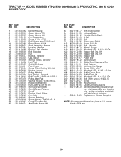
... 817 00 06-16 Screw Hexwsh Thd 3/8-16 x 1 59 532 14 10-43 Guard, Tuv Idler (94) 60 532 19 94-71 Arm Brake Mower LH KEY PART NO. Cable Screw 5/16-18 Bolt, Shoulder Wheel, Gauge Washer 13/32 x 1-1/4 x 12 Ga. inches 1 inch = 25.4 mm 39 Stud Fastener...32 x 13/16 x 12 Ga. pulley/nut/washer and blade bolt/washers not included) Replacement Mower, Complete NOTE: All component dimensions given in U.S. MODEL NUMBER YTH21K46 (96045002901), PRODUCT NO. 960 45 00-29 MOWER DECK KEY PART NO. TRACTOR - - RH Keeper Belt Pulley Idler Spring Return Cable Clutch Manual w/Spr. LH Keeper...
... 817 00 06-16 Screw Hexwsh Thd 3/8-16 x 1 59 532 14 10-43 Guard, Tuv Idler (94) 60 532 19 94-71 Arm Brake Mower LH KEY PART NO. Cable Screw 5/16-18 Bolt, Shoulder Wheel, Gauge Washer 13/32 x 1-1/4 x 12 Ga. inches 1 inch = 25.4 mm 39 Stud Fastener...32 x 13/16 x 12 Ga. pulley/nut/washer and blade bolt/washers not included) Replacement Mower, Complete NOTE: All component dimensions given in U.S. MODEL NUMBER YTH21K46 (96045002901), PRODUCT NO. 960 45 00-29 MOWER DECK KEY PART NO. TRACTOR - - RH Keeper Belt Pulley Idler Spring Return Cable Clutch Manual w/Spr. LH Keeper...

Owners Manual
Page 40
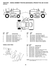
...-70 100 873 93 06-00 101 532 40 70-03 DESCRIPTION Screw 3/8-16 x .75 Smgml Tap/R.Z Link Lift Susp. MODEL NUMBER YTH21K46 (96045002901), PRODUCT NO. 960 45 00-29 MOWER LIFT 87 7 10 3 97 90 98 89 100 2 91 88 97 87 89 101* 89 87 lift-tex_17_r3 *Key 91 may... Grip, Lever Spring Torsion Pin Cotter 7/16 Bow Tie Lock Spring Lift Assist Washer Clear Zinc Pin Cotter 5/16 Bow Tie Lock Link Lift Susp Mower Rear KEY PART NO. inches 1 inch = 25.4 mm 40 Front Mower Nut Center Lock 3/8-16 unc Link Asm Lift Fixed NOTE: All component dimensions given in U.S. TRACTOR - -
...-70 100 873 93 06-00 101 532 40 70-03 DESCRIPTION Screw 3/8-16 x .75 Smgml Tap/R.Z Link Lift Susp. MODEL NUMBER YTH21K46 (96045002901), PRODUCT NO. 960 45 00-29 MOWER LIFT 87 7 10 3 97 90 98 89 100 2 91 88 97 87 89 101* 89 87 lift-tex_17_r3 *Key 91 may... Grip, Lever Spring Torsion Pin Cotter 7/16 Bow Tie Lock Spring Lift Assist Washer Clear Zinc Pin Cotter 5/16 Bow Tie Lock Link Lift Susp Mower Rear KEY PART NO. inches 1 inch = 25.4 mm 40 Front Mower Nut Center Lock 3/8-16 unc Link Asm Lift Fixed NOTE: All component dimensions given in U.S. TRACTOR - -
Owners Manual
Page 42
...-82 532 44 41-83 532 44 41-84 Decal, Battery Dnge/Poi Decal, Mower Warning Decal, Mower V-Belt Schematic Decal, Bypass Pad, Footrest, LH Pad, Footrest, RH Manual, Owner's (English) Manual, Owner's (Spanish) KEY PART NO. MODEL NUMBER YTH21K46 (96045002901), PRODUCT NO. 960 45 00-29 DECALS 47 2 56 2 8 3 1 9 10 KEY NO. 1 2 3 4 5 6 7 8 12...
...-82 532 44 41-83 532 44 41-84 Decal, Battery Dnge/Poi Decal, Mower Warning Decal, Mower V-Belt Schematic Decal, Bypass Pad, Footrest, LH Pad, Footrest, RH Manual, Owner's (English) Manual, Owner's (Spanish) KEY PART NO. MODEL NUMBER YTH21K46 (96045002901), PRODUCT NO. 960 45 00-29 DECALS 47 2 56 2 8 3 1 9 10 KEY NO. 1 2 3 4 5 6 7 8 12...

Parts List
Page 14
Keeper Belt Eng. MODEL NUMBER YTH21K46 (96045002601), PRODUCT NO. 960 45 00-26 MOWER DECK KEY PART NO. Bolt 3/8-16 unc x 2-1/4 Gr. 5 Screw Washout Port Quick Connect Coupling Mandrel Assembly (Includes housing, shaft ...Bolt, Shoulder Wheel, Gauge Washer 13/32 x 1-1/4 x 12 Ga. LH Keeper Belt Eng. DESCRIPTION 1 532 44 23-82 Mower Housing 2 532 40 55-06 Cover Mandrel RH 3 532 40 55-07 Cover Mandrel LH 6 532 19 51-86 Arm Suspension... 14 10-43 Guard, Tuv Idler (94) 60 532 19 94-71 Arm Brake Mower LH KEY PART NO. pulley/nut/washer and blade bolt/washers not included) Replacement...
Keeper Belt Eng. MODEL NUMBER YTH21K46 (96045002601), PRODUCT NO. 960 45 00-26 MOWER DECK KEY PART NO. Bolt 3/8-16 unc x 2-1/4 Gr. 5 Screw Washout Port Quick Connect Coupling Mandrel Assembly (Includes housing, shaft ...Bolt, Shoulder Wheel, Gauge Washer 13/32 x 1-1/4 x 12 Ga. LH Keeper Belt Eng. DESCRIPTION 1 532 44 23-82 Mower Housing 2 532 40 55-06 Cover Mandrel RH 3 532 40 55-07 Cover Mandrel LH 6 532 19 51-86 Arm Suspension... 14 10-43 Guard, Tuv Idler (94) 60 532 19 94-71 Arm Brake Mower LH KEY PART NO. pulley/nut/washer and blade bolt/washers not included) Replacement...

Parts List
Page 15
...-00 101 532 40 70-03 DESCRIPTION Screw 3/8-16 x .75 Smgml Tap/R.Z Link Lift Susp. TRACTOR - - MODEL NUMBER YTH21K46 (96045002601), PRODUCT NO. 960 45 00-26 MOWER LIFT 87 7 10 3 97 90 98 89 100 2 91 88 97 87 89 101* 89 87 lift-tex_17_r3 *Key ...91 may be substituted for Key 101 KEY NO. 2 3 7 10 87 88 89 90 91 PART NO. 532 42 20-27 ...Cotter 7/16 Bow Tie Lock Spring Lift Assist Washer Clear Zinc Pin Cotter 5/16 Bow Tie Lock Link Lift Susp Mower Rear KEY PART NO.
...-00 101 532 40 70-03 DESCRIPTION Screw 3/8-16 x .75 Smgml Tap/R.Z Link Lift Susp. TRACTOR - - MODEL NUMBER YTH21K46 (96045002601), PRODUCT NO. 960 45 00-26 MOWER LIFT 87 7 10 3 97 90 98 89 100 2 91 88 97 87 89 101* 89 87 lift-tex_17_r3 *Key ...91 may be substituted for Key 101 KEY NO. 2 3 7 10 87 88 89 90 91 PART NO. 532 42 20-27 ...Cotter 7/16 Bow Tie Lock Spring Lift Assist Washer Clear Zinc Pin Cotter 5/16 Bow Tie Lock Link Lift Susp Mower Rear KEY PART NO.

Parts List
Page 17
MODEL NUMBER YTH21K46 (96045002601), PRODUCT NO. 960 45 00-26 DECALS 2 56 2 8 9 3 1 4 12 KEY NO. 1 2 3 4 5 6 8 PART NO. Tube) NOTE: All component dimensions given in U.S. DESCRIPTION 532 41 91-38 532 42 91-96 532 43 95-66 532 17 05-63 ... 96-82 532 44 24 72 532 44 24-73 Decal, Battery Dnge/Poi Decal, Mower V-Belt Schematic Decal, Bypass Pad, Footrest, LH Pad, Footrest, RH Manual, Owner's (English) Manual, Owner's (Spanish) KEY NO. 1 2 3 4 5 6 7 8 9 10 11 - - PART NO. TRACTOR - - DESCRIPTION 532 05 91-92 532 06 51-39 532 13 83-36...
MODEL NUMBER YTH21K46 (96045002601), PRODUCT NO. 960 45 00-26 DECALS 2 56 2 8 9 3 1 4 12 KEY NO. 1 2 3 4 5 6 8 PART NO. Tube) NOTE: All component dimensions given in U.S. DESCRIPTION 532 41 91-38 532 42 91-96 532 43 95-66 532 17 05-63 ... 96-82 532 44 24 72 532 44 24-73 Decal, Battery Dnge/Poi Decal, Mower V-Belt Schematic Decal, Bypass Pad, Footrest, LH Pad, Footrest, RH Manual, Owner's (English) Manual, Owner's (Spanish) KEY NO. 1 2 3 4 5 6 7 8 9 10 11 - - PART NO. TRACTOR - - DESCRIPTION 532 05 91-92 532 06 51-39 532 13 83-36...


