
Owners Manual
Page 3
...instructions 6 Safety instructions 7 General use 7 Controls 9 Operation 10 Movement/Transport 11 Storage 11 Children 11 Fuel System 12 Maintenance 13 Protective Equipment 14 Personal Equipment 14 Set-Up 15 Equipment set-up 15 Controls 18 Presentation 18 Main Components and Operating Instructions ...the Sludge Reservoir 34 Idle Adjustment 34 Ignition System 35 Adjusting the Drive Belt 36 Disassembling & Reassembling the Blade, Pockets & Teeth 37 Removing & Refitting the Wheels .......... 38 Adjusting the Brake 38 Two Minute Rule 39 Cleaning & Washing 39 Lubrication 40 ...
...instructions 6 Safety instructions 7 General use 7 Controls 9 Operation 10 Movement/Transport 11 Storage 11 Children 11 Fuel System 12 Maintenance 13 Protective Equipment 14 Personal Equipment 14 Set-Up 15 Equipment set-up 15 Controls 18 Presentation 18 Main Components and Operating Instructions ...the Sludge Reservoir 34 Idle Adjustment 34 Ignition System 35 Adjusting the Drive Belt 36 Disassembling & Reassembling the Blade, Pockets & Teeth 37 Removing & Refitting the Wheels .......... 38 Adjusting the Brake 38 Two Minute Rule 39 Cleaning & Washing 39 Lubrication 40 ...

Owners Manual
Page 37
... all screws and nuts when the adjustment is complete. CHECK CLUTCH & PULLEY ALIGN USING INSIDE FACE 8011-229chg Disassembling and reassembling the blade, pockets and teeth IMPORTANT INFORMATION The cutters and pockets are turned in ./lbs. (17513 / 19264 N•m). 7. Check that the tooth cutters are mounted on threads and re-torqued...
... all screws and nuts when the adjustment is complete. CHECK CLUTCH & PULLEY ALIGN USING INSIDE FACE 8011-229chg Disassembling and reassembling the blade, pockets and teeth IMPORTANT INFORMATION The cutters and pockets are turned in ./lbs. (17513 / 19264 N•m). 7. Check that the tooth cutters are mounted on threads and re-torqued...
Owners Manual
Page 38
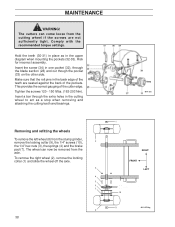
... (32-33). Insert a bar through the blade section (28) and out though the pocket (33) on the other side. Risk for incorrect assembly. Hold the teeth (30-31) in place as in the cutting wheel to act as a stop when removing and attaching the cutting...
... (32-33). Insert a bar through the blade section (28) and out though the pocket (33) on the other side. Risk for incorrect assembly. Hold the teeth (30-31) in place as in the cutting wheel to act as a stop when removing and attaching the cutting...

Parts List
Page 9
LEFT TOOTH 7 ........ 539 02 02-31 ........1 ........ COMPLET SET OF CUTTING TEETH (includes COUNTER BORE POCKET (4 EA THREADED POCKETS (4 EA LEFT TOOTH (4 EA RIGHT TOOTH (4 EA SOCKET HEAD SCREWS (8 EA) 5 ... ........1 ........ SOCKET HEAD SCREW (2 EA TWO SCREWS ARE REQUIRED PER POCKET 10 ...... 539 20 07-52 ........1 ........ CUTTING TEETH, COMPLETE (includes RIGHT TOOTH (4 EA LEFT TOOTH (4 EA 539 11 01-44 ........ 1 ........ CUTTING WHEEL ASSEMBLY (NO TEETH) 4 ........ 539 02 02-28 ........1 ........ QTY. BEARING, FLANGE (includes BEARING (1 EA BOLT 3/8-16 X 1 3/4...
LEFT TOOTH 7 ........ 539 02 02-31 ........1 ........ COMPLET SET OF CUTTING TEETH (includes COUNTER BORE POCKET (4 EA THREADED POCKETS (4 EA LEFT TOOTH (4 EA RIGHT TOOTH (4 EA SOCKET HEAD SCREWS (8 EA) 5 ... ........1 ........ SOCKET HEAD SCREW (2 EA TWO SCREWS ARE REQUIRED PER POCKET 10 ...... 539 20 07-52 ........1 ........ CUTTING TEETH, COMPLETE (includes RIGHT TOOTH (4 EA LEFT TOOTH (4 EA 539 11 01-44 ........ 1 ........ CUTTING WHEEL ASSEMBLY (NO TEETH) 4 ........ 539 02 02-28 ........1 ........ QTY. BEARING, FLANGE (includes BEARING (1 EA BOLT 3/8-16 X 1 3/4...