
Parts Manual
Page 17
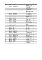
... ANCHOR 19 586 27 79-01 STICKER 20 579 57 12-01 LABEL 21 590 85 50-01 BOX 22 596 33 98-01 TOOL AUTOMOWER 310, 2020- Safety Blade, 300 pcs 1 Wire, Blister Pack, (50 m) 1 Wire (150 m) 1 Wire, Blister Pack, (150 m) 1 Wire (250 m)... - Safety Blade, Blister Pack, 9 pcs 1 Long Life - Remark QTY KIT Installation KIT S: Wire (150 m), Staples (300 Connectors (3 pcs), pcs), 1 Couplers (5 pcs) Installation KIT M: Wire (250 m), Staples (400 Connectors (3 pcs), pcs), 1 Couplers (5 pcs) Installation KIT L: Wire (400 m), Staples (600 Connectors (5 pcs), pcs), 1 Couplers ...
... ANCHOR 19 586 27 79-01 STICKER 20 579 57 12-01 LABEL 21 590 85 50-01 BOX 22 596 33 98-01 TOOL AUTOMOWER 310, 2020- Safety Blade, 300 pcs 1 Wire, Blister Pack, (50 m) 1 Wire (150 m) 1 Wire, Blister Pack, (150 m) 1 Wire (250 m)... - Safety Blade, Blister Pack, 9 pcs 1 Long Life - Remark QTY KIT Installation KIT S: Wire (150 m), Staples (300 Connectors (3 pcs), pcs), 1 Couplers (5 pcs) Installation KIT M: Wire (250 m), Staples (400 Connectors (3 pcs), pcs), 1 Couplers (5 pcs) Installation KIT L: Wire (400 m), Staples (600 Connectors (5 pcs), pcs), 1 Couplers ...
Owner Manual
Page 2
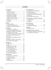
... 1.10 Keypad 10 2 Safety 2.1 Safety definitions 11 2.2 General safety instructions 11 2.3 Safety instructions for operation 13 3 Installation 3.1 Introduction - Start 34 4.4 Operating mode - Installation 16 3.2 Before the installation of the wires........... 16 3.3 Before the installation of the product........16 3.4 Installation of the product 21 3.5 To put the wire into position with stakes...22 3.6 To bury the...
... 1.10 Keypad 10 2 Safety 2.1 Safety definitions 11 2.2 General safety instructions 11 2.3 Safety instructions for operation 13 3 Installation 3.1 Introduction - Start 34 4.4 Operating mode - Installation 16 3.2 Before the installation of the wires........... 16 3.3 Before the installation of the product........16 3.4 Installation of the product 21 3.5 To put the wire into position with stakes...22 3.6 To bury the...
Owner Manual
Page 5
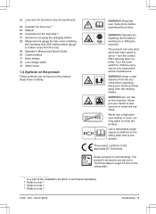
...1 1220 - 001 - 08.07.2019 Introduction - 5 The product's emissions are set to 0 before working on the rating plate. 1 Is a part of the Installation kit which is broken loose from the box) 29. Alarm decal 1.4 Symbols on the product These symbols can only start when the main switch is...maintenance. Turn the main switch to 1 and the correct PIN code has been entered. WARNING: Do not ride on the product. Connector for help when installing the boundary wire (the measurement gauge is purchased separately. 2 Refer to note 1 3 Refer to note 1 4 Refer to the symbol. Measurement gauge for...
...1 1220 - 001 - 08.07.2019 Introduction - 5 The product's emissions are set to 0 before working on the rating plate. 1 Is a part of the Installation kit which is broken loose from the box) 29. Alarm decal 1.4 Symbols on the product These symbols can only start when the main switch is...maintenance. Turn the main switch to 1 and the correct PIN code has been entered. WARNING: Do not ride on the product. Connector for help when installing the boundary wire (the measurement gauge is purchased separately. 2 Refer to note 1 3 Refer to note 1 4 Refer to the symbol. Measurement gauge for...

Owner Manual
Page 6
...are sensitive to electrostatic discharge (ESD). The product will not cut the grass do not charge the battery. 1.5 Symbols on the battery The installation function for manual settings for the product are set. When the product charges the symbol flashes. Read the user instructions. 6 - A broken...products are set in the charging station but do to the timer function. For Automower® Connect and Connect@Home. The GPS-supported navigation is where all settings for the accessories for the installation. Introduction 1220 - 001 - 08.07.2019 The settings function is where the...
...are sensitive to electrostatic discharge (ESD). The product will not cut the grass do not charge the battery. 1.5 Symbols on the battery The installation function for manual settings for the product are set. When the product charges the symbol flashes. Read the user instructions. 6 - A broken...products are set in the charging station but do to the timer function. For Automower® Connect and Connect@Home. The GPS-supported navigation is where all settings for the accessories for the installation. Introduction 1220 - 001 - 08.07.2019 The settings function is where the...

Owner Manual
Page 9
... Set date Time format Date format Low- Low Mid High High+ Accessories Information Connect@Home** Automower Connect Headlight*** Mower house * Automower® 315/315X **Automower® 310/315 ***Automower® 315X 1220 - 001 - 08.07.2019 Introduction - 9 1.8 Menu structure overview - 2 Installation Lawn coverage Find charging station Advanced GPS Auto*** Guide Area 1-3 Delay Disable More time Boundary...
... Set date Time format Date format Low- Low Mid High High+ Accessories Information Connect@Home** Automower Connect Headlight*** Mower house * Automower® 315/315X **Automower® 310/315 ***Automower® 315X 1220 - 001 - 08.07.2019 Introduction - 9 1.8 Menu structure overview - 2 Installation Lawn coverage Find charging station Advanced GPS Auto*** Guide Area 1-3 Delay Disable More time Boundary...
Owner Manual
Page 16
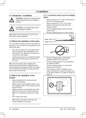
...lawn. 3.3.1 To examine where to the boundary wire. Note: Holes with stakes or bury them. Note: Refer to www.husqvarna.com for more information about installation. 3.2 Before the installation of the wires You can select to attach the wires with water in the lawn can use a dethatcher on a level ...not, attach the boundary wire or guide wire with protection from the sun. • If the charging station is much lower. 3.3 Before the installation of the product • Make a blueprint of the charging station. • Put the charging station near an outdoor power outlet. • ...
...lawn. 3.3.1 To examine where to the boundary wire. Note: Holes with stakes or bury them. Note: Refer to www.husqvarna.com for more information about installation. 3.2 Before the installation of the wires You can select to attach the wires with water in the lawn can use a dethatcher on a level ...not, attach the boundary wire or guide wire with protection from the sun. • If the charging station is much lower. 3.3 Before the installation of the product • Make a blueprint of the charging station. • Put the charging station near an outdoor power outlet. • ...
Owner Manual
Page 17
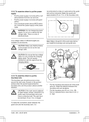
... change the power supply. CAUTION: Do not put as accessories. The coil causes interference with good airflow. • Use a residual-current device (RCD) when you install the boundary wire and guide wire. Note: Make a blueprint of electrical shock. Low-voltage cables of the boundary wire. Adapt the distance between the guide... where the guide wire will be connected. recommended to water bodies, slopes, precipices or a from the charging station. There is 1220 - 001 - 08.07.2019 Installation - 17
... change the power supply. CAUTION: Do not put as accessories. The coil causes interference with good airflow. • Use a residual-current device (RCD) when you install the boundary wire and guide wire. Note: Make a blueprint of electrical shock. Low-voltage cables of the boundary wire. Adapt the distance between the guide... where the guide wire will be connected. recommended to water bodies, slopes, precipices or a from the charging station. There is 1220 - 001 - 08.07.2019 Installation - 17
Owner Manual
Page 18
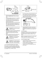
...from the obstacle together. • Put the 2 sections of the slope. 3.3.3.2 Passages A passage is a section that has boundary wire on gravel. • If you install the boundary wire. Put the wires in the same stake. • Make an eyelet (F) where the guide wire is less than 2 m / 6.5 ft. Example: ...the slope with boundary wire. • For slopes steeper than 10% along the outer edge of boundary wire in the same stake. 18 - wide, install a guide wire through the passage. 3.3.3.3 To make an island • Put the boundary wire to and around the obstacle to make sharp bends when...
...from the obstacle together. • Put the 2 sections of the slope. 3.3.3.2 Passages A passage is a section that has boundary wire on gravel. • If you install the boundary wire. Put the wires in the same stake. • Make an eyelet (F) where the guide wire is less than 2 m / 6.5 ft. Example: ...the slope with boundary wire. • For slopes steeper than 10% along the outer edge of boundary wire in the same stake. 18 - wide, install a guide wire through the passage. 3.3.3.3 To make an island • Put the boundary wire to and around the obstacle to make sharp bends when...
Owner Manual
Page 19
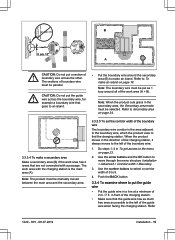
... charging station is the area adjacent to the boundary wire, which the product uses to 9. 4. in To get access to move through the menu structure Installation > Advanced > Corridor width > Boundary. 3. Push the BACK button. 3.3.4 To examine where to put the guide wire across the other. B 0 cm / 0" A CAUTION: Do not put a section... on page 23. 2. Note: When the product cuts grass in a line at a minimum of 0 to find the charging station. Refer 1220 - 001 - 08.07.2019 Installation - 19
... charging station is the area adjacent to the boundary wire, which the product uses to 9. 4. in To get access to move through the menu structure Installation > Advanced > Corridor width > Boundary. 3. Push the BACK button. 3.3.4 To examine where to put the guide wire across the other. B 0 cm / 0" A CAUTION: Do not put a section... on page 23. 2. Note: When the product cuts grass in a line at a minimum of 0 to find the charging station. Refer 1220 - 001 - 08.07.2019 Installation - 19

Owner Manual
Page 20
.... Use the number buttons to the boundary wire 3. The settings can set the Lawn coverage function on page 26. • Use the GPS Assisted Navigation. Installation 1220 - 001 - 08.07.2019 When the product moves in To set the product to leave the guide wire after a certain distance (C). smaller than 2 m... width of the guide wire A The guide corridor is the area adjacent to the guide wire, which are connected by a narrow passage (B), you install the guide wire. • If the work area has a slope, put in the secondary area and select Secondary area mode. Use the arrow ...
.... Use the number buttons to the boundary wire 3. The settings can set the Lawn coverage function on page 26. • Use the GPS Assisted Navigation. Installation 1220 - 001 - 08.07.2019 When the product moves in To set the product to leave the guide wire after a certain distance (C). smaller than 2 m... width of the guide wire A The guide corridor is the area adjacent to the guide wire, which are connected by a narrow passage (B), you install the guide wire. • If the work area has a slope, put in the secondary area and select Secondary area mode. Use the arrow ...

Owner Manual
Page 21
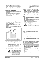
...To bury the boundary wire or the guide wire on the charging station. 3.4.2 To install the boundary wire 1. CAUTION: Do not make new holes in the ground with the power supply unit supplied by Husqvarna. above each connector. 5. Refer to To put the boundary wire in . Condensed...of electrical shock. 5. Close the connector with the supplied screws. Put the low-voltage cable in the charging station plate. 3.4 Installation of the product 3.4.1 To install the charging station WARNING: Obey national regulations about the charging station. Refer to To examine where to the ground with a pair...
...To bury the boundary wire or the guide wire on the charging station. 3.4.2 To install the boundary wire 1. CAUTION: Do not make new holes in the ground with the power supply unit supplied by Husqvarna. above each connector. 5. Refer to To put the boundary wire in . Condensed...of electrical shock. 5. Close the connector with the supplied screws. Put the low-voltage cable in the charging station plate. 3.4 Installation of the product 3.4.1 To install the charging station WARNING: Obey national regulations about the charging station. Refer to To examine where to the ground with a pair...
Owner Manual
Page 22
..., or a screw terminal block that the stakes hold the boundary wire and the guide wire against the ground. Put the wire ends into position. 4. Installation 1220 - 001 - 08.07.2019 Close the connector with an edge cutter or a straight shovel. • Put the boundary wire or the guide wire...pin on the boundary wire. 8. Connect the guide wire to the ground with insulation tape are not satisfactory splices. cause the wire to install the extension. 2. Refer to install the extension. 3. CAUTION: Make sure that is insulated with stakes or bury the guide wire in the ground. Note: Make sure ...
..., or a screw terminal block that the stakes hold the boundary wire and the guide wire against the ground. Put the wire ends into position. 4. Installation 1220 - 001 - 08.07.2019 Close the connector with an edge cutter or a straight shovel. • Put the boundary wire or the guide wire...pin on the boundary wire. 8. Connect the guide wire to the ground with insulation tape are not satisfactory splices. cause the wire to install the extension. 2. Refer to install the extension. 3. CAUTION: Make sure that is insulated with stakes or bury the guide wire in the ground. Note: Make sure ...

Owner Manual
Page 23
Note: Make sure that you must operate each work area. 3.9.1 To get access to make a note of the installation. Put the boundary wire or the guide wire into position with a Automower® 310. 1220 - 001 - 08.07.2019 Installation - 23 Push the STOP button. 2. Note: It is not possible to table below. 3. Push the MENU...
Note: Make sure that you must operate each work area. 3.9.1 To get access to make a note of the installation. Put the boundary wire or the guide wire into position with a Automower® 310. 1220 - 001 - 08.07.2019 Installation - 23 Push the STOP button. 2. Note: It is not possible to table below. 3. Push the MENU...
Owner Manual
Page 24
.... The product locks if the PINcode has not been entered in To get access to move through the menu structure Timer > Overview Timer settings > Overview. 3. Installation 1220 - 001 - 08.07.2019
.... The product locks if the PINcode has not been entered in To get access to move through the menu structure Timer > Overview Timer settings > Overview. 3. Installation 1220 - 001 - 08.07.2019
Owner Manual
Page 25
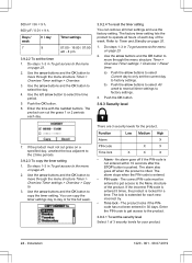
... page 23. 2. Note: The Weather timer is done. 1. At all user setting is reset if the product stops to mow. 1220 - 001 - 08.07.2019 Installation - 25 Do steps 1-3 in the standard manner and starts to operate for more than 50 hours or if a Reset of 1 to the menu on page...
... page 23. 2. Note: The Weather timer is done. 1. At all user setting is reset if the product stops to mow. 1220 - 001 - 08.07.2019 Installation - 25 Do steps 1-3 in the standard manner and starts to operate for more than 50 hours or if a Reset of 1 to the menu on page...

Owner Manual
Page 26
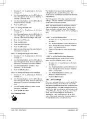
...by carrying out some of the area. Push the arrow buttons to the complete work area. The % is recommended to move through the menu structure Installation > Lawn coverage. 3. a) Measure the area. Push the BACK button. 3.9.5.3 To set the Lawn coverage function 1. Push the BACK button. ...the manual settings in To get access to move through the menu structure Installation > Lawn coverage > Area 1-3 > How far? 7. Do steps 1-3 in the Lawn coverage menu. 3.9.5.1 To disable the GPS Assisted Navigation Only for Automower® 315X. 1. Use the arrow buttons and the OK button to...
...by carrying out some of the area. Push the arrow buttons to the complete work area. The % is recommended to move through the menu structure Installation > Lawn coverage. 3. a) Measure the area. Push the BACK button. 3.9.5.3 To set the Lawn coverage function 1. Push the BACK button. ...the manual settings in To get access to move through the menu structure Installation > Lawn coverage > Area 1-3 > How far? 7. Do steps 1-3 in the Lawn coverage menu. 3.9.5.1 To disable the GPS Assisted Navigation Only for Automower® 315X. 1. Use the arrow buttons and the OK button to...
Owner Manual
Page 27
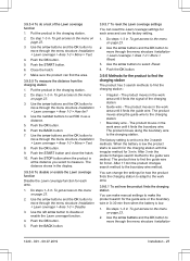
.... The product moves in To get access to mix the 3 search methods. After 3 min the product changes search method to move through the menu structure Installation > Lawn coverage > Area 1-3 > More > Reset. 3. You can change the settings for each area and use the factory setting. 1. Put the ...The product has 3 search methods to make the product search for 8 min. The product moves in To get access to move through the menu structure Installation > Lawn coverage > Area 1-3 > How far? 4. The product tries to search for the charging station with the irregular method for each area. ...
.... The product moves in To get access to mix the 3 search methods. After 3 min the product changes search method to move through the menu structure Installation > Lawn coverage > Area 1-3 > More > Reset. 3. You can change the settings for each area and use the factory setting. 1. Put the ...The product has 3 search methods to make the product search for 8 min. The product moves in To get access to move through the menu structure Installation > Lawn coverage > Area 1-3 > How far? 4. The product tries to search for the charging station with the irregular method for each area. ...
Owner Manual
Page 28
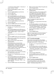
... exit angle between 90°-270°. The exit angles can be set the time. 5. Use the number buttons to move through the menu structure Installation > Find the charging station > Overview of search methods > Charging station range. 3. Push the down arrow button. 5. Push the OK button. ... the charging station, change the signal range of search methods > Boundary > More > Test right / Test left arrow button to move through the menu structure Installation > Advanced > Exit angles > Sector 1 or 2. 3. Do steps 1-3 in To get access to the menu on page 23. 2. Change the position ...
... exit angle between 90°-270°. The exit angles can be set the time. 5. Use the number buttons to move through the menu structure Installation > Find the charging station > Overview of search methods > Charging station range. 3. Push the down arrow button. 5. Push the OK button. ... the charging station, change the signal range of search methods > Boundary > More > Test right / Test left arrow button to move through the menu structure Installation > Advanced > Exit angles > Sector 1 or 2. 3. Do steps 1-3 in To get access to the menu on page 23. 2. Change the position ...
Owner Manual
Page 29
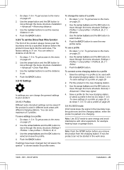
...buttons to the menu on page 23. 2. Push the BACK button. Do steps 1-4 in the work area. 1220 - 001 - 08.07.2019 Installation - 29 You can select a distance of product settings can not be saved if the product is charging. Save the settings in cm. 4. To change... the general settings to move through the menu structure Installation > Advanced > Drive Past Wire. 3. Do steps 1-3 in To get access to set the reverse distance in a profile to a profile on page 23...
...buttons to the menu on page 23. 2. Push the BACK button. Do steps 1-4 in the work area. 1220 - 001 - 08.07.2019 Installation - 29 You can select a distance of product settings can not be saved if the product is charging. Save the settings in cm. 4. To change... the general settings to move through the menu structure Installation > Advanced > Drive Past Wire. 3. Do steps 1-3 in To get access to set the reverse distance in a profile to a profile on page 23...
Owner Manual
Page 30
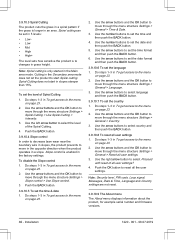
... time & date 1. Use the arrow buttons to set the date format and then push the BACK button. 3.9.10.6 To set the level of Spiral Cutting 1. Installation 1220 - 001 - 08.07.2019 To set the language 1. Use the left arrow button to select Proceed with reset of the Spiral Cutting. 4. Use the...
... time & date 1. Use the arrow buttons to set the date format and then push the BACK button. 3.9.10.6 To set the level of Spiral Cutting 1. Installation 1220 - 001 - 08.07.2019 To set the language 1. Use the left arrow button to select Proceed with reset of the Spiral Cutting. 4. Use the...


