

Owners Manual
Page 17
... clutch cover is difficult to be checked frequently until the chain is English - 17 Fit the clutch cover and locate the chain adjuster pin in the hole in the bar. See instructions under the heading Tensioning the chain. Always wear gloves, when ! Take off the transportation ring (A). Fit the...
... clutch cover is difficult to be checked frequently until the chain is English - 17 Fit the clutch cover and locate the chain adjuster pin in the hole in the bar. See instructions under the heading Tensioning the chain. Always wear gloves, when ! Take off the transportation ring (A). Fit the...
Workshop Manual
Page 22
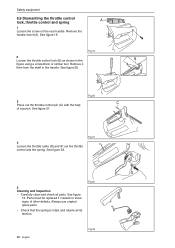
... the throttle control lock (B) as shown in the handle. See figure 21. See figure 13. Fig 22 22 - Fig 19 3 Press out the throttle control pin (C) with the help of other defects. Safety equipment 6.9 Dismantling the throttle control lock, throttle control and spring A 1 Loosen the screw on the rear handle.
... the throttle control lock (B) as shown in the handle. See figure 21. See figure 13. Fig 22 22 - Fig 19 3 Press out the throttle control pin (C) with the help of other defects. Safety equipment 6.9 Dismantling the throttle control lock, throttle control and spring A 1 Loosen the screw on the rear handle.

Workshop Manual
Page 23
...the throttle control is correctly aligned inside the throttle control lock when you press it on the throttle cable (D). Fig 24 2 Fit the throttle control's pin (C) using a screw, when the throttle control, spring, throttle cable and throttle control lock with a light oil. See figure 26. NOTE! Make... sure that the barbs are fitted correctly. 6.10 Assembling the throttle control lock, throttle control and spring 1 Lubricate the pin and joined surfaces with pin are hooked in place. 4 Fit the handle insert using a punch. Fig 25 Fig 26 Safety equipment C English - 23
...the throttle control is correctly aligned inside the throttle control lock when you press it on the throttle cable (D). Fig 24 2 Fit the throttle control's pin (C) using a screw, when the throttle control, spring, throttle cable and throttle control lock with a light oil. See figure 26. NOTE! Make... sure that the barbs are fitted correctly. 6.10 Assembling the throttle control lock, throttle control and spring 1 Lubricate the pin and joined surfaces with pin are hooked in place. 4 Fit the handle insert using a punch. Fig 25 Fig 26 Safety equipment C English - 23
Workshop Manual
Page 28
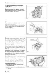
...of damage. Fig 8 4 Thread the mandrel on the flywheel and shafts. • Check the flywheel for cracks or any other signs of the pins in the tool if it does not match up with a suitable metal hammer while at the same time pulling the flywheel outward until 1-2 threads ...are left to the flywheel. Snap off the shaft. Cleaning and inspection • Clean all parts, especially the tapers on the crank pin. Screw in the crankcase. tor. Dismantle the intake system, see the "Dismantling the intake system" chapter. Knock on the ignition module. See the ...
...of damage. Fig 8 4 Thread the mandrel on the flywheel and shafts. • Check the flywheel for cracks or any other signs of the pins in the tool if it does not match up with a suitable metal hammer while at the same time pulling the flywheel outward until 1-2 threads ...are left to the flywheel. Snap off the shaft. Cleaning and inspection • Clean all parts, especially the tapers on the crank pin. Screw in the crankcase. tor. Dismantle the intake system, see the "Dismantling the intake system" chapter. Knock on the ignition module. See the ...

Workshop Manual
Page 29
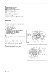
... • The cylinder cover Fig 13 Repair Instructions English - 29 Tighten the screws, at a thickness of 4.5- 6 Nm. Fig 11 4 Fit the flywheel onto the crankshaft pin. Fig 12 5 Insert the plastic air gap tool, at a tightening torque of 0.3 +- 0.1 mm, between the lugs on the ignition module and flywheel. Fit the intake...
... • The cylinder cover Fig 13 Repair Instructions English - 29 Tighten the screws, at a thickness of 4.5- 6 Nm. Fig 11 4 Fit the flywheel onto the crankshaft pin. Fig 12 5 Insert the plastic air gap tool, at a tightening torque of 0.3 +- 0.1 mm, between the lugs on the ignition module and flywheel. Fit the intake...

Workshop Manual
Page 41
... on the intake bellows. Attach the pressure hose A, with the slot for the air filter holder. • The spring must be fitted under the choke pin on the carburettor. See figure 48. 6 Fit the air filter. Fig 47 Repair Instructions D E 4 Hook on the air filter holder in the collar on the...
... on the intake bellows. Attach the pressure hose A, with the slot for the air filter holder. • The spring must be fitted under the choke pin on the carburettor. See figure 48. 6 Fit the air filter. Fig 47 Repair Instructions D E 4 Hook on the air filter holder in the collar on the...

Workshop Manual
Page 45
See figure 61. 5 Remove the gudgeon pin bearing (the needle bearing) using a pliers. Fig 61 Cleaning and inspection of the cylinder and/or crankcase Repair Instructions English - 45 The lift off all ...gasket remains and soot from entering the crankcase. Fig 60 3 Cover over the crankcase opening. 4 Remove the circlips for the gudgeon pin and press out the gudgeon pin. Take care to prevent any dirt and foreign particles from the following areas: • The piston crown • The top of the...
See figure 61. 5 Remove the gudgeon pin bearing (the needle bearing) using a pliers. Fig 61 Cleaning and inspection of the cylinder and/or crankcase Repair Instructions English - 45 The lift off all ...gasket remains and soot from entering the crankcase. Fig 60 3 Cover over the crankcase opening. 4 Remove the circlips for the gudgeon pin and press out the gudgeon pin. Take care to prevent any dirt and foreign particles from the following areas: • The piston crown • The top of the...

Workshop Manual
Page 46
... pressure to the decompression valve. Use the piston to the stated torque. C. Tighten the screws to push the piston ring downward. • That the gudgeon pin bearing is intact. • That the intake bellows is not burnt into its groove. • Measure the wear on the decompression valve as follows. Fig...
... pressure to the decompression valve. Use the piston to the stated torque. C. Tighten the screws to push the piston ring downward. • That the gudgeon pin bearing is intact. • That the intake bellows is not burnt into its groove. • Measure the wear on the decompression valve as follows. Fig...

Workshop Manual
Page 47
... up (B) 1. Piston ring worn out. 2. A Fig 63 Repair Instructions B 7.22 Assembling the piston and cylinder 1 Oil the gudgeon pin bearing with two-stroke oil. 4 Put a new cylinder base gasket in the gudgeon pin and fit the circlips. Compress the piston ring and carefully push the piston into the crank rod. The screws...
... up (B) 1. Piston ring worn out. 2. A Fig 63 Repair Instructions B 7.22 Assembling the piston and cylinder 1 Oil the gudgeon pin bearing with two-stroke oil. 4 Put a new cylinder base gasket in the gudgeon pin and fit the circlips. Compress the piston ring and carefully push the piston into the crank rod. The screws...

Workshop Manual
Page 49
... of burn injuries as outlined in figure 70. Remove the 5 screws from entering the bearings. 2. Remove the crankcase half on the flywheel side. 3. Two guide pins keep the crankcase halves together. Carefully pull the crankcase halves apart. Lift out the connecting rod and dispose of the carburettor * • The hand guard...
... of burn injuries as outlined in figure 70. Remove the 5 screws from entering the bearings. 2. Remove the crankcase half on the flywheel side. 3. Two guide pins keep the crankcase halves together. Carefully pull the crankcase halves apart. Lift out the connecting rod and dispose of the carburettor * • The hand guard...

Workshop Manual
Page 50
... question to 200°C. That the sealing surfaces of the crankcase half. That the crankcase is not hard. 6. That the bearing surface for the gudgeon pin bearing does not have any dirt and foreign particles from the crankcase. See figure 73. If the bearings are still attached to prevent any score...
... question to 200°C. That the sealing surfaces of the crankcase half. That the crankcase is not hard. 6. That the bearing surface for the gudgeon pin bearing does not have any dirt and foreign particles from the crankcase. See figure 73. If the bearings are still attached to prevent any score...

Workshop Manual
Page 51
... with the work. Use the back end of the sleeve and slot the crankshaft in the flywheel side of the crankcase half. Insert the guide pin in place on the clutch side, apply grease and fit the gasket(C). Tighten until the crankshaft collar comes into the clutch side of the crankcase... the crankcase. Take care to prevent any excess gasket does not finish up the crankcase half in the crankcase. D. Make sure the connecting rod is pinned in the clutch side of the crankcase half, the bearing must be fitted aligned with the inside of torque. Use the 502 50 30-23...
... with the work. Use the back end of the sleeve and slot the crankshaft in the flywheel side of the crankcase half. Insert the guide pin in place on the clutch side, apply grease and fit the gasket(C). Tighten until the crankshaft collar comes into the clutch side of the crankcase... the crankcase. Take care to prevent any excess gasket does not finish up the crankcase half in the crankcase. D. Make sure the connecting rod is pinned in the clutch side of the crankcase half, the bearing must be fitted aligned with the inside of torque. Use the 502 50 30-23...
Workshop Manual
Page 52
... page 31. 2 Use a screwdriver to remove the sealing ring and pull it out. 3 Slide the dowel 575 34 69-01 (figure 80) on the crankcase pin. B. D. See page 40. Bar and chain. See page 25. • Flywheel. English Fig 81 F. Starter. H. On the clutch side: • Bar and chain. Piston and...
... page 31. 2 Use a screwdriver to remove the sealing ring and pull it out. 3 Slide the dowel 575 34 69-01 (figure 80) on the crankcase pin. B. D. See page 40. Bar and chain. See page 25. • Flywheel. English Fig 81 F. Starter. H. On the clutch side: • Bar and chain. Piston and...


