Owner's Manual
Page 4
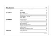
Table of Contents INTRODUCTION INSTALLATION PROGRAMMING OPERATIONS Read This Before Installing Thermostat Features What You Need Remove Old Thermostat Wire Labeling Mount Wallplate and Thermostat Selector Switches Setting Time and Day Auto Programming Personal Program Schedule Manual Programming Weekday / Weekend Programming 7-Day Programming Reviewing Programs Reviewing the Current Temperature Setting System Selector Switch Fan Switch 4-5 6 8 10 10 11 12 14 16 17 18 19 19 21 22 23 24 24 (continued)
Table of Contents INTRODUCTION INSTALLATION PROGRAMMING OPERATIONS Read This Before Installing Thermostat Features What You Need Remove Old Thermostat Wire Labeling Mount Wallplate and Thermostat Selector Switches Setting Time and Day Auto Programming Personal Program Schedule Manual Programming Weekday / Weekend Programming 7-Day Programming Reviewing Programs Reviewing the Current Temperature Setting System Selector Switch Fan Switch 4-5 6 8 10 10 11 12 14 16 17 18 19 19 21 22 23 24 24 (continued)
Owner's Manual
Page 5
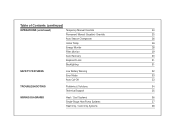
Table of Contents (continued) OPERATIONS (continued) Temporary Manual Override 24 Permanent Manual (Vacation) Override 25 Auto Season Changeover 26 Home Today 26 Energy Monitor 28 Filter Monitor 29 Auto Recovery 30 Keyboard Lock 31 Backlighting 31 SAFETY FEATURES Low Battery Warning 32 Error Mode 33 Auto Cut-Off 33 TROUBLESHOOTING Problems & Solutions 34 Technical Support 35 WIRING DIAGRAMS Heat / Cool Systems 36 Single-Stage Heat Pump Systems 37 Heat Only / Cool Only Systems 38
Table of Contents (continued) OPERATIONS (continued) Temporary Manual Override 24 Permanent Manual (Vacation) Override 25 Auto Season Changeover 26 Home Today 26 Energy Monitor 28 Filter Monitor 29 Auto Recovery 30 Keyboard Lock 31 Backlighting 31 SAFETY FEATURES Low Battery Warning 32 Error Mode 33 Auto Cut-Off 33 TROUBLESHOOTING Problems & Solutions 34 Technical Support 35 WIRING DIAGRAMS Heat / Cool Systems 36 Single-Stage Heat Pump Systems 37 Heat Only / Cool Only Systems 38
Owner's Manual
Page 6
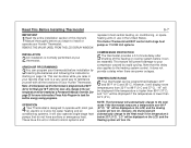
... on the LCD, and the Heating system will prevent damage to operate with all the functions of your Hunter Thermostat. This can be done while you begin to install or operate your Hunter Thermostat. Press Auto Program to 99°F (0°C and 37°C). However, it can program your...can be displayed on the LCD, and the Cooling system will be restarted. "LO" will turn On. represent most gas, oil, electric or 2-wire hot water heating and air conditioning systems. It will also operate single-stage heat pumps that this thermostat is below 32°F (0°C). Note:...
... on the LCD, and the Heating system will prevent damage to operate with all the functions of your Hunter Thermostat. This can be done while you begin to install or operate your Hunter Thermostat. Press Auto Program to 99°F (0°C and 37°C). However, it can program your...can be displayed on the LCD, and the Cooling system will be restarted. "LO" will turn On. represent most gas, oil, electric or 2-wire hot water heating and air conditioning systems. It will also operate single-stage heat pumps that this thermostat is below 32°F (0°C). Note:...

Owner's Manual
Page 10
...INSTALLATION 10-11 What You Need This thermostat includes two #8 slotted screws and two wall anchors for wires. s Remove existing thermostat cover. Some thermostats will have the following tools and materials. If wires are not visible, they may be removed. To install your thermostat, you should have screws or ...s Slotted Screwdriver(s) s Phillips Screwdriver s Hammer s Electric drill and 3/16" bit s Two 1.5 V (AA) size alkaline batteries Remove Old Thermostat CAUTION: Do not remove any wiring from existing thermostat before reading the instructions carefully. Again, look for mounting...
...INSTALLATION 10-11 What You Need This thermostat includes two #8 slotted screws and two wall anchors for wires. s Remove existing thermostat cover. Some thermostats will have the following tools and materials. If wires are not visible, they may be removed. To install your thermostat, you should have screws or ...s Slotted Screwdriver(s) s Phillips Screwdriver s Hammer s Electric drill and 3/16" bit s Two 1.5 V (AA) size alkaline batteries Remove Old Thermostat CAUTION: Do not remove any wiring from existing thermostat before reading the instructions carefully. Again, look for mounting...
Owner's Manual
Page 11
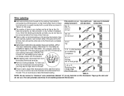
... RH RH RH If you follow the labeling procedures correctly, you may want to tape them from the existing thermostat terminals. Tape up the wire and do GY Air Conditioning Compressor Y/Y1 not always comply with a code letter as eight, or any terminal on your existing thermostat.) IGNORE... do not have to be as few as two (for heat only systems), as many wires there are. This wire provides electricity to complete the circuit. s If hole in your then mark the wire and connect to thermostat connected to a terminal point on that no terminal marking on your system...
... RH RH RH If you follow the labeling procedures correctly, you may want to tape them from the existing thermostat terminals. Tape up the wire and do GY Air Conditioning Compressor Y/Y1 not always comply with a code letter as eight, or any terminal on your existing thermostat.) IGNORE... do not have to be as few as two (for heat only systems), as many wires there are. This wire provides electricity to complete the circuit. s If hole in your then mark the wire and connect to thermostat connected to a terminal point on that no terminal marking on your system...

Owner's Manual
Page 12
... Drill holes with 3/16" bit and gently tap anchors into wall anchor and tighten. (See Figure 3.) OB RC G Y/Y1 W RH Figure 2 NOTE: 5-wire Systems Figure 3 If your thermostat by pressing the release tab on the bottom of the thermostat. (See Figure 2.) s Position wallplate on the... Hunter wallplate. Insert mounting screws provided into the holes until flush with those on wall and pull existing wires through large opening . Then level for plastic anchors provided if your existing holes do not ...
... Drill holes with 3/16" bit and gently tap anchors into wall anchor and tighten. (See Figure 3.) OB RC G Y/Y1 W RH Figure 2 NOTE: 5-wire Systems Figure 3 If your thermostat by pressing the release tab on the bottom of the thermostat. (See Figure 2.) s Position wallplate on the... Hunter wallplate. Insert mounting screws provided into the holes until flush with those on wall and pull existing wires through large opening . Then level for plastic anchors provided if your existing holes do not ...
Owner's Manual
Page 13
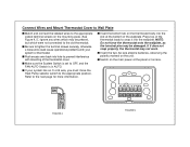
...more information. s If your system or thermostat. Refer to the appropriate position. s Be sure to tighten the terminal screws securely, otherwise a loose wire could cause operational problems with mounting of the wallplate. W RH RC G Y/Y1 O/B RH x+x+x+ RH FIGURE 4 FIGURE 5 NOTE: Do not force... the System Switch is in AUTO. s Switch on the thermostat body into the wallplate. Connect Wires and Mount Thermostat Cover to Wall Plate s Match and connect the labeled wires to the appropriate coded terminal screws on the unit. s Insert the two AA size alkaline batteries...
...more information. s If your system or thermostat. Refer to the appropriate position. s Be sure to tighten the terminal screws securely, otherwise a loose wire could cause operational problems with mounting of the wallplate. W RH RC G Y/Y1 O/B RH x+x+x+ RH FIGURE 4 FIGURE 5 NOTE: Do not force... the System Switch is in AUTO. s Switch on the thermostat body into the wallplate. Connect Wires and Mount Thermostat Cover to Wall Plate s Match and connect the labeled wires to the appropriate coded terminal screws on the unit. s Insert the two AA size alkaline batteries...
Owner's Manual
Page 14
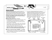
... Heat Pump selector (NORMAL - If you have an electric furnace, test to suit your needs. If your heat pump system has an "O" wire, slide the switch to "B" for your reversing valve that matches your system, the system type must be specified by selector switches on as expected...control your Reversing Valve type. Leave it in the NORMAL position. System Selector Switches: s Heating system selector (HG - Leave it in this Hunter thermostat to OFF before removing the thermostat from the wall. F°/C° selector 12 Hr./24 Hr. (SW5) selector (SW6) Recovery ...
... Heat Pump selector (NORMAL - If you have an electric furnace, test to suit your needs. If your heat pump system has an "O" wire, slide the switch to "B" for your reversing valve that matches your system, the system type must be specified by selector switches on as expected...control your Reversing Valve type. Leave it in the NORMAL position. System Selector Switches: s Heating system selector (HG - Leave it in this Hunter thermostat to OFF before removing the thermostat from the wall. F°/C° selector 12 Hr./24 Hr. (SW5) selector (SW6) Recovery ...
Owner's Manual
Page 34
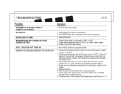
...power to opposite position 1. Look for the correct day setting. 1. wait and check. (Compressor protection delay.) 4. Make sure your system only uses 4-wires, be as much as a 4 minute delay before changing from Heat or Cool. 3. Check that the time is in for two seconds. 1. ... 5. Check that the system selector switch is set properly to "AM" or "PM". 2. The thermostat may be sure the jumper wire is closed properly. 7. Check the position of the Furnace or Heat Pump selector switch: Normal / O / B. Check battery connections and batteries. 2. ...
...power to opposite position 1. Look for the correct day setting. 1. wait and check. (Compressor protection delay.) 4. Make sure your system only uses 4-wires, be as much as a 4 minute delay before changing from Heat or Cool. 3. Check that the time is in for two seconds. 1. ... 5. Check that the system selector switch is set properly to "AM" or "PM". 2. The thermostat may be sure the jumper wire is closed properly. 7. Check the position of the Furnace or Heat Pump selector switch: Normal / O / B. Check battery connections and batteries. 2. ...

Owner's Manual
Page 36
No Connection 36-37 WIRING DIAGRAMS 4-wire Heat/Cool System Jumper RC RH Heat/Cool 24V Supply THERMOSTAT G Fan Relay W Y O/B X Heat Relay or Valve Cool Contactor 5-wire Heat/Cool System THERMOSTAT RC RH G Cool Heat Fan 24V Supply 24V Supply Relay W Y O/B X Heat Relay Cool or Valve Contactor X -
No Connection 36-37 WIRING DIAGRAMS 4-wire Heat/Cool System Jumper RC RH Heat/Cool 24V Supply THERMOSTAT G Fan Relay W Y O/B X Heat Relay or Valve Cool Contactor 5-wire Heat/Cool System THERMOSTAT RC RH G Cool Heat Fan 24V Supply 24V Supply Relay W Y O/B X Heat Relay Cool or Valve Contactor X -
Owner's Manual
Page 37
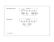
No Connection Single-stage Heat Pump 2-wire Heat Only Jumper RC RH Heat Pump 24V Supply THERMOSTAT G W X Fan Relay Y O/B Compressor Reversing Contactor Valve THERMOSTAT RC RH G W Y O/B X X X X Heat 24V Supply Heat Relay or Valve X -
No Connection Single-stage Heat Pump 2-wire Heat Only Jumper RC RH Heat Pump 24V Supply THERMOSTAT G W X Fan Relay Y O/B Compressor Reversing Contactor Valve THERMOSTAT RC RH G W Y O/B X X X X Heat 24V Supply Heat Relay or Valve X -

Owner's Manual
Page 38
WIRING DIAGRAMS 38 3-wire Heat Only Jumper THERMOSTAT RC RH G W Y O/B X X X Heat Fan 24V Supply Relay Heat Relay or Valve 3-wire Cool Only THERMOSTAT RC RH G X Cool Fan 24V Supply Relay W Y O/B X X Cool Contactor X - No Connection
WIRING DIAGRAMS 38 3-wire Heat Only Jumper THERMOSTAT RC RH G W Y O/B X X X Heat Fan 24V Supply Relay Heat Relay or Valve 3-wire Cool Only THERMOSTAT RC RH G X Cool Fan 24V Supply Relay W Y O/B X X Cool Contactor X - No Connection


