Owner's Manual
Page 4
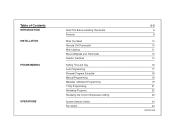
Table of Contents INTRODUCTION INSTALLATION PROGRAMMING OPERATIONS Read This Before Installing Thermostat Features What You Need Remove Old Thermostat Wire Labeling Mount Wallplate and Thermostat Selector Switches Setting Time and Day Auto Programming Personal Program Schedule Manual Programming Weekday / Weekend Programming 7-Day Programming Reviewing Programs Reviewing the Current Temperature Setting System Selector Switch Fan Switch 4-5 6 8 10 10 11 12 14 16 17 18 19 19 21 22 23 24 24 (continued)
Table of Contents INTRODUCTION INSTALLATION PROGRAMMING OPERATIONS Read This Before Installing Thermostat Features What You Need Remove Old Thermostat Wire Labeling Mount Wallplate and Thermostat Selector Switches Setting Time and Day Auto Programming Personal Program Schedule Manual Programming Weekday / Weekend Programming 7-Day Programming Reviewing Programs Reviewing the Current Temperature Setting System Selector Switch Fan Switch 4-5 6 8 10 10 11 12 14 16 17 18 19 19 21 22 23 24 24 (continued)
Owner's Manual
Page 5
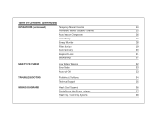
Table of Contents (continued) OPERATIONS (continued) Temporary Manual Override 24 Permanent Manual (Vacation) Override 25 Auto Season Changeover 26 Home Today 26 Energy Monitor 28 Filter Monitor 29 Auto Recovery 30 Keyboard Lock 31 Backlighting 31 SAFETY FEATURES Low Battery Warning 32 Error Mode 33 Auto Cut-Off 33 TROUBLESHOOTING Problems & Solutions 34 Technical Support 35 WIRING DIAGRAMS Heat / Cool Systems 36 Single-Stage Heat Pump Systems 37 Heat Only / Cool Only Systems 38
Table of Contents (continued) OPERATIONS (continued) Temporary Manual Override 24 Permanent Manual (Vacation) Override 25 Auto Season Changeover 26 Home Today 26 Energy Monitor 28 Filter Monitor 29 Auto Recovery 30 Keyboard Lock 31 Backlighting 31 SAFETY FEATURES Low Battery Warning 32 Error Mode 33 Auto Cut-Off 33 TROUBLESHOOTING Problems & Solutions 34 Technical Support 35 WIRING DIAGRAMS Heat / Cool Systems 36 Single-Stage Heat Pump Systems 37 Heat Only / Cool Only Systems 38
Owner's Manual
Page 6
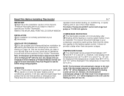
... on the LCD, and the Cooling system will also operate single-stage heat pumps that this delay also applies to install or operate your Hunter Thermostat. Note that do not have 24-volt or millivolt control systems and COMPRESSOR PROTECTION 5 The thermostat provides a 3.5 minute delay after ... below 32°F (0°C). It does not provide a delay when there are power outages. represent most gas, oil, electric or 2-wire hot water heating and air conditioning systems. It will turn On. Read This Before Installing Thermostat 6-7 IMPORTANT 1Read the entire installation section of your...
... on the LCD, and the Cooling system will also operate single-stage heat pumps that this delay also applies to install or operate your Hunter Thermostat. Note that do not have 24-volt or millivolt control systems and COMPRESSOR PROTECTION 5 The thermostat provides a 3.5 minute delay after ... below 32°F (0°C). It does not provide a delay when there are power outages. represent most gas, oil, electric or 2-wire hot water heating and air conditioning systems. It will turn On. Read This Before Installing Thermostat 6-7 IMPORTANT 1Read the entire installation section of your...

Owner's Manual
Page 10
... Screwdriver s Hammer s Electric drill and 3/16" bit s Two 1.5 V (AA) size alkaline batteries Remove Old Thermostat CAUTION: Do not remove any wiring from existing thermostat before reading the instructions carefully. Again, look for screws, tabs, etc. Some models have doors that must first be connected to the... back of the wallplate. s IMPORTANT! Once wall mounting plate is exposed, look for wires. If wires are not visible, they may be removed. INSTALLATION 10-11 What You Need This thermostat includes two #8 slotted screws and two ...
... Screwdriver s Hammer s Electric drill and 3/16" bit s Two 1.5 V (AA) size alkaline batteries Remove Old Thermostat CAUTION: Do not remove any wiring from existing thermostat before reading the instructions carefully. Again, look for screws, tabs, etc. Some models have doors that must first be connected to the... back of the wallplate. s IMPORTANT! Once wall mounting plate is exposed, look for wires. If wires are not visible, they may be removed. INSTALLATION 10-11 What You Need This thermostat includes two #8 slotted screws and two ...
Owner's Manual
Page 11
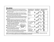
... not fall back into wall opening, you do not have to non-battery powered thermostats. Table A NOTE: Do not connect a "Common" wire (sometimes labeled "C") to the wall. This wire provides electricity to be as few as shown in between. RH, R, VR or 4 24 Volt RH RH RH If you follow the labeling... no hot or cold air can be concerned about how many as eight, or any terminal on your existing thermostat.) IGNORE THE COLOR OF THE WIRES since these existing thermostat is with label shown terminal shown terminal points is usually marked with the standard. W RH s After labeling...
... not fall back into wall opening, you do not have to non-battery powered thermostats. Table A NOTE: Do not connect a "Common" wire (sometimes labeled "C") to the wall. This wire provides electricity to be as few as shown in between. RH, R, VR or 4 24 Volt RH RH RH If you follow the labeling... no hot or cold air can be concerned about how many as eight, or any terminal on your existing thermostat.) IGNORE THE COLOR OF THE WIRES since these existing thermostat is with label shown terminal shown terminal points is usually marked with the standard. W RH s After labeling...

Owner's Manual
Page 12
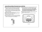
.... Insert mounting screws provided into the holes until flush with those on the wallplate. Mark holes for appearance. s Reposition wallplate to wall, pulling wires through large opening . s Drill holes with 3/16" bit and gently tap anchors into wall anchor and tighten. (See Figure 3.) OB RC...your thermostat has one wire marked R or RH (4-wire system), then leave the jumper wire between the RH and RC terminals. Otherwise, if you have separate RH and RC wires (5-wire system), then remove the jumper wire between the RH and RC terminals on the Hunter wallplate. INSTALLATION 12-13...
.... Insert mounting screws provided into the holes until flush with those on the wallplate. Mark holes for appearance. s Reposition wallplate to wall, pulling wires through large opening . s Drill holes with 3/16" bit and gently tap anchors into wall anchor and tighten. (See Figure 3.) OB RC...your thermostat has one wire marked R or RH (4-wire system), then leave the jumper wire between the RH and RC terminals. Otherwise, if you have separate RH and RC wires (5-wire system), then remove the jumper wire between the RH and RC terminals on the Hunter wallplate. INSTALLATION 12-13...
Owner's Manual
Page 13
... onto the wallplate, as the terminal pins may be present, but which were not connected to tighten the terminal screws securely, otherwise a loose wire could cause operational problems with mounting of the thermostat cover. s Insert the two AA size alkaline batteries, observing the polarity marked on the main... the wallplate. Press top of the thermostat body to the next page for more information. s Push excess wire back into hole to prevent interference with your system has an O or B wire, you must move the Heat Pump selector switch to OFF, and the FAN-AUTO Switch is in AUTO....
... onto the wallplate, as the terminal pins may be present, but which were not connected to tighten the terminal screws securely, otherwise a loose wire could cause operational problems with mounting of the thermostat cover. s Insert the two AA size alkaline batteries, observing the polarity marked on the main... the wallplate. Press top of the thermostat body to the next page for more information. s Push excess wire back into hole to prevent interference with your system has an O or B wire, you must move the Heat Pump selector switch to OFF, and the FAN-AUTO Switch is in AUTO....
Owner's Manual
Page 14
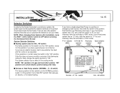
...to suit your Reversing Valve type. switch HG - B switch) The factory position for certain electric systems having a fan relay. Leave it in this Hunter thermostat to OFF before removing the thermostat from the wall. O - There are also other systems. "HE" position is for this position if you have...or emergency heat source), then slide the switch to the position that activates in the cooling mode. If your heat pump system has an "O" wire, slide the switch to "O" for your system, the system type must be specified by selector switches on within a minute of the thermostat ...
...to suit your Reversing Valve type. switch HG - B switch) The factory position for certain electric systems having a fan relay. Leave it in this Hunter thermostat to OFF before removing the thermostat from the wall. O - There are also other systems. "HE" position is for this position if you have...or emergency heat source), then slide the switch to the position that activates in the cooling mode. If your heat pump system has an "O" wire, slide the switch to "O" for your system, the system type must be specified by selector switches on within a minute of the thermostat ...
Owner's Manual
Page 34
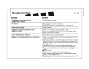
... then the thermostat requires a larger room temperature change before the Heat or Cool system turns On - Replace batteries. 6. Make sure your system only uses 4-wires, be as much as a 4 minute delay before changing from Heat or Cool. 3. Press RESET button with a small pin and hold in the AUTO ... DOES NOT TURN ON HEATING OR COOLING DOES NOT GO ON OR OFF Solution 1. Remove clear mylar sticker 1. The thermostat may be sure the jumper wire is not in the correct position ("HEAT," "COOL" or "AUTO"). 2. wait and check. (Compressor protection delay.) 4. If your furnace blower door ...
... then the thermostat requires a larger room temperature change before the Heat or Cool system turns On - Replace batteries. 6. Make sure your system only uses 4-wires, be as much as a 4 minute delay before changing from Heat or Cool. 3. Press RESET button with a small pin and hold in the AUTO ... DOES NOT TURN ON HEATING OR COOLING DOES NOT GO ON OR OFF Solution 1. Remove clear mylar sticker 1. The thermostat may be sure the jumper wire is not in the correct position ("HEAT," "COOL" or "AUTO"). 2. wait and check. (Compressor protection delay.) 4. If your furnace blower door ...

Owner's Manual
Page 36
WIRING DIAGRAMS 4-wire Heat/Cool System Jumper RC RH Heat/Cool 24V Supply THERMOSTAT G Fan Relay W Y O/B X Heat Relay or Valve Cool Contactor 5-wire Heat/Cool System THERMOSTAT RC RH G Cool Heat Fan 24V Supply 24V Supply Relay W Y O/B X Heat Relay Cool or Valve Contactor X - No Connection 36-37
WIRING DIAGRAMS 4-wire Heat/Cool System Jumper RC RH Heat/Cool 24V Supply THERMOSTAT G Fan Relay W Y O/B X Heat Relay or Valve Cool Contactor 5-wire Heat/Cool System THERMOSTAT RC RH G Cool Heat Fan 24V Supply 24V Supply Relay W Y O/B X Heat Relay Cool or Valve Contactor X - No Connection 36-37
Owner's Manual
Page 37
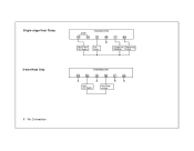
No Connection Single-stage Heat Pump 2-wire Heat Only Jumper RC RH Heat Pump 24V Supply THERMOSTAT G W X Fan Relay Y O/B Compressor Reversing Contactor Valve THERMOSTAT RC RH G W Y O/B X X X X Heat 24V Supply Heat Relay or Valve X -
No Connection Single-stage Heat Pump 2-wire Heat Only Jumper RC RH Heat Pump 24V Supply THERMOSTAT G W X Fan Relay Y O/B Compressor Reversing Contactor Valve THERMOSTAT RC RH G W Y O/B X X X X Heat 24V Supply Heat Relay or Valve X -

Owner's Manual
Page 38
No Connection WIRING DIAGRAMS 38 3-wire Heat Only Jumper THERMOSTAT RC RH G W Y O/B X X X Heat Fan 24V Supply Relay Heat Relay or Valve 3-wire Cool Only THERMOSTAT RC RH G X Cool Fan 24V Supply Relay W Y O/B X X Cool Contactor X -
No Connection WIRING DIAGRAMS 38 3-wire Heat Only Jumper THERMOSTAT RC RH G W Y O/B X X X Heat Fan 24V Supply Relay Heat Relay or Valve 3-wire Cool Only THERMOSTAT RC RH G X Cool Fan 24V Supply Relay W Y O/B X X Cool Contactor X -


