Owner's Manual
Page 3
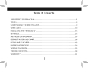
Table of Contents important information...5 Tools...6 uninstalling the existing unit...9 wire labels...10 installing the thermostat...13 settings...23 methods of operation...27 Default Programs Chart...36 ICONS AND FEATURES...43 Important features...54 Wiring Diagrams...55 troubleshooting...58 Warranty...61 3
Table of Contents important information...5 Tools...6 uninstalling the existing unit...9 wire labels...10 installing the thermostat...13 settings...23 methods of operation...27 Default Programs Chart...36 ICONS AND FEATURES...43 Important features...54 Wiring Diagrams...55 troubleshooting...58 Warranty...61 3
Owner's Manual
Page 7
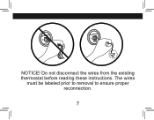
RC Y G W RC Y G W w NOTICE! The wires must be labeled prior to removal to ensure proper reconnection. 7 Do not disconnect the wires from the existing thermostat before reading these instructions.
RC Y G W RC Y G W w NOTICE! The wires must be labeled prior to removal to ensure proper reconnection. 7 Do not disconnect the wires from the existing thermostat before reading these instructions.
Owner's Manual
Page 9
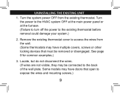
Some models may have multiple covers, screws or other locking devices that open to expose the wires and mounting screws.) 9 See page 8 for common examples.) 3. Locate, but do not disconnect the wires. (If wires are not visible, they may have doors that must be connected to the existing thermostat before removal could damage your.... (Failure to turn off the power to the back of the wall plate. uninstalling the existing unit 1. Remove the existing thermostat cover to access the wires from the existing thermostat.
Some models may have multiple covers, screws or other locking devices that open to expose the wires and mounting screws.) 9 See page 8 for common examples.) 3. Locate, but do not disconnect the wires. (If wires are not visible, they may have doors that must be connected to the existing thermostat before removal could damage your.... (Failure to turn off the power to the back of the wall plate. uninstalling the existing unit 1. Remove the existing thermostat cover to access the wires from the existing thermostat.

Owner's Manual
Page 10
Y1 G W/B Y/0 RC RH wire labels if your existing thermostat is marked... label the wire with this sticker: RH / R / VR / 4 24 Volt RH RC / VC 24 Volt cool RC Y / C* / M / O air conditioning compressor W / H / B G / F Y1 heating Y/0 W/B fan G heat pump compressor Y1 10
Y1 G W/B Y/0 RC RH wire labels if your existing thermostat is marked... label the wire with this sticker: RH / R / VR / 4 24 Volt RH RC / VC 24 Volt cool RC Y / C* / M / O air conditioning compressor W / H / B G / F Y1 heating Y/0 W/B fan G heat pump compressor Y1 10

Owner's Manual
Page 11
... contact a qualified HVAC technician.) W RC Y G W Note: Wire colors do not always comply with standards, so wire color should be used only for proper identification. *If wires marked Y & C are both present, C may want to secure the wires to the wall as electrical tape.) 11 Refer to any terminal. If... you disconnect them. You may be a Common wire and should not be capped with an approved electrical connector, such as you have a wire marked C, do not connect it to the existing terminal designation for non-battery powered thermostats. ...
... contact a qualified HVAC technician.) W RC Y G W Note: Wire colors do not always comply with standards, so wire color should be used only for proper identification. *If wires marked Y & C are both present, C may want to secure the wires to the wall as electrical tape.) 11 Refer to any terminal. If... you disconnect them. You may be a Common wire and should not be capped with an approved electrical connector, such as you have a wire marked C, do not connect it to the existing terminal designation for non-battery powered thermostats. ...
Owner's Manual
Page 13
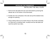
Remove the wall plate from the new thermostat by pressing the release tab on the Hunter wall plate, or if there are no existing holes, visually level the wall plate and mark the wall for two holes. 13 If the existing holes do not match those on the bottom of the thermostat. 2. installing the thermostat INSTALLING THE WALL PLATE 1. Position the new wall plate on the wall and pull the labeled wires through the opening. 3.
Remove the wall plate from the new thermostat by pressing the release tab on the Hunter wall plate, or if there are no existing holes, visually level the wall plate and mark the wall for two holes. 13 If the existing holes do not match those on the bottom of the thermostat. 2. installing the thermostat INSTALLING THE WALL PLATE 1. Position the new wall plate on the wall and pull the labeled wires through the opening. 3.

Owner's Manual
Page 15
Insert the mounting screws through the opening. Reposition the wall plate on the wall, pulling the wires through the wall plate and into the holes until they are flush with the wall. (Do not use plastic anchors if you encounter a stud in the wall.) 6. Verify that the wall plate is visually level and securely tighten both screws. 15 Tap the plastic anchors into the anchors. installing the thermostat, cont. 4. Remove the wall plate and drill two 3/16" holes where marked. 5.
Insert the mounting screws through the opening. Reposition the wall plate on the wall, pulling the wires through the wall plate and into the holes until they are flush with the wall. (Do not use plastic anchors if you encounter a stud in the wall.) 6. Verify that the wall plate is visually level and securely tighten both screws. 15 Tap the plastic anchors into the anchors. installing the thermostat, cont. 4. Remove the wall plate and drill two 3/16" holes where marked. 5.

Owner's Manual
Page 17
... be individually wrapped in place. 2. Loosen, but do not provide both an RH and RC wire, remove this jumper. If you do not have both an RH and RC wire. Note: A jumper wire has been provided, connecting the RC and RH terminals for systems that do not remove, the terminal screws. ...CONNECTING THE WIRES Jumper G RC RH Y W 1. Match and connect the wires from the wall to prevent interference. 17 If you have both an RH and RC wire, leave the jumper in electrical tape and carefully pushed back into the wall to...
... be individually wrapped in place. 2. Loosen, but do not provide both an RH and RC wire, remove this jumper. If you do not have both an RH and RC wire. Note: A jumper wire has been provided, connecting the RC and RH terminals for systems that do not remove, the terminal screws. ...CONNECTING THE WIRES Jumper G RC RH Y W 1. Match and connect the wires from the wall to prevent interference. 17 If you have both an RH and RC wire, leave the jumper in electrical tape and carefully pushed back into the wall to...
Owner's Manual
Page 55
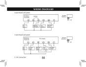
4-wire Heat/Cool System Wallplate Terminals G Fan Relay Wiring Diagrams Jumper Rc Rh Y/O X Heat/Cool 24V Supply Cool Contactor W/B Y1 X Heat Relay or Valve System Selector STD - No Connection 55 HP X - HP 5-wire Heat/Cool System Wallplate Terminals G Rc Fan Cool 24V Relay Supply No Jumper Rh Heat 24V Supply Y/O W/B Y1 Cool Contactor X Heat Relay or Valve System Selector STD -
4-wire Heat/Cool System Wallplate Terminals G Fan Relay Wiring Diagrams Jumper Rc Rh Y/O X Heat/Cool 24V Supply Cool Contactor W/B Y1 X Heat Relay or Valve System Selector STD - No Connection 55 HP X - HP 5-wire Heat/Cool System Wallplate Terminals G Rc Fan Cool 24V Relay Supply No Jumper Rh Heat 24V Supply Y/O W/B Y1 Cool Contactor X Heat Relay or Valve System Selector STD -

Owner's Manual
Page 56
Single-stage Heat Pump Wallplate Terminals G Fan Relay Jumper Rc Rh X Heat Pump 24V Supply Y/O W/B Cool OR Heat Mode Mode Reversing Valve Y1 Compressor Contactor System Selector STD - HP 2-wire Heat Only Wallplate Terminals G X Jumper Rc Rh X Heat 24V or Millivolt Supply Connect to Proper Reversing Valve Terminal. HP X - Y/O W/B Y1 X X Heat Relay or Valve System Selector STD - No Connection 56 Wiring Diagrams, Cont.
Single-stage Heat Pump Wallplate Terminals G Fan Relay Jumper Rc Rh X Heat Pump 24V Supply Y/O W/B Cool OR Heat Mode Mode Reversing Valve Y1 Compressor Contactor System Selector STD - HP 2-wire Heat Only Wallplate Terminals G X Jumper Rc Rh X Heat 24V or Millivolt Supply Connect to Proper Reversing Valve Terminal. HP X - Y/O W/B Y1 X X Heat Relay or Valve System Selector STD - No Connection 56 Wiring Diagrams, Cont.
Owner's Manual
Page 57
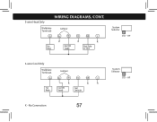
Wallplate Terminals Jumper G Rc Rh Y/O W/B Y1 X X X Fan Heat 24V Heat Relay Relay Supply or Valve System Selector STD - HP 3-wire Cool Only Wallplate Terminals Jumper G Rc Rh Y/O W/B Y1 X X X Fan Cool 24V Relay Supply Cool Contactor X - HP 3-wire Heat Only Wiring Diagrams, Cont. No Connection 57 System Selector STD -
Wallplate Terminals Jumper G Rc Rh Y/O W/B Y1 X X X Fan Heat 24V Heat Relay Relay Supply or Valve System Selector STD - HP 3-wire Cool Only Wallplate Terminals Jumper G Rc Rh Y/O W/B Y1 X X X Fan Cool 24V Relay Supply Cool Contactor X - HP 3-wire Heat Only Wiring Diagrams, Cont. No Connection 57 System Selector STD -
Owner's Manual
Page 59
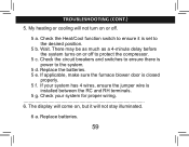
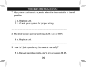
... much as a 4-minute delay before the system turns on or off to protect the compressor. 5 c. Replace the batteries. 5 e. troubleshooting (cont.) 5. If your system for proper wiring 6. Check your system has 4 wires, ensure the jumper wire is closed properly. 5 f. My heating or cooling will not stay illuminated. 6 a.
... much as a 4-minute delay before the system turns on or off to protect the compressor. 5 c. Replace the batteries. 5 e. troubleshooting (cont.) 5. If your system for proper wiring 6. Check your system has 4 wires, ensure the jumper wire is closed properly. 5 f. My heating or cooling will not stay illuminated. 6 a.
Owner's Manual
Page 60
The LCD screen permanently reads HI, LO, or ERR. 8 a. How do I just operate my thermostat manually? 9 a. Replace unit. 7 b. Replace unit 9. Manual operation instructions are on pages 28-31. 60 My system continues to operate when the thermostat is in the off position. 7 a. troubleshooting (cont.) 7. Check your system for proper wiring. 8.
The LCD screen permanently reads HI, LO, or ERR. 8 a. How do I just operate my thermostat manually? 9 a. Replace unit. 7 b. Replace unit 9. Manual operation instructions are on pages 28-31. 60 My system continues to operate when the thermostat is in the off position. 7 a. troubleshooting (cont.) 7. Check your system for proper wiring. 8.
Owner's Manual
Page 30
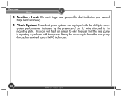
Features Alerts 6 3. It may be necessary to the mounting plate. Check System: Some heat pump systems are equipped with the system. This icon will flash on screen to alert the user that the heat pump is running. 4. Auxiliary Heat: On multi-stage heat pumps this alert indicates your second stage heat is reporting a problem with the ability to check system performance, indicated by the presence of an "L" wire attached to have the heat pump checked or serviced by an HVAC technician. 30 44040-01 • 05/11/2010
Features Alerts 6 3. It may be necessary to the mounting plate. Check System: Some heat pump systems are equipped with the system. This icon will flash on screen to alert the user that the heat pump is running. 4. Auxiliary Heat: On multi-stage heat pumps this alert indicates your second stage heat is reporting a problem with the ability to check system performance, indicated by the presence of an "L" wire attached to have the heat pump checked or serviced by an HVAC technician. 30 44040-01 • 05/11/2010


