Installation Guide
Page 1
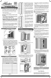
...Figure 2. ©2010 Hunter Fan Company C G Figure 8. Figure 11. You may be using the bubble level on the mounting plate Figure 7., then install the other locking devices that matches the wire label then lower the lever. 1 44272, 44277 Programmable Thermostat Installation Sheet Preparation Gathering ...Tools and Warnings 1 This thermostat is located underneath the wire holes, between the RH and RC terminals on the...
...Figure 2. ©2010 Hunter Fan Company C G Figure 8. Figure 11. You may be using the bubble level on the mounting plate Figure 7., then install the other locking devices that matches the wire label then lower the lever. 1 44272, 44277 Programmable Thermostat Installation Sheet Preparation Gathering ...Tools and Warnings 1 This thermostat is located underneath the wire holes, between the RH and RC terminals on the...
Installation Guide
Page 2
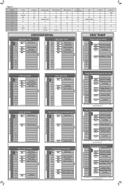
... not be present. Figure 4. Single Stage Heat Pump W/Heat Reversing Thermostat Mounting Plate R Y G L O B Aux/E Y2 C R Heat 24V Supply Y Compressor Contact G Fan Relay L System Monitor* B Heat Relay / Valve E Auxiliary Heat C Common* * The common wire "C" and system monitor wire "L" may or may not be present. Hunter R Y E O B G L C Carrier R Y or Y1 W2 E O G L or F C Coleman R Y W2 E B G L X Comfortmaker R Y W1 Jumper...
... not be present. Figure 4. Single Stage Heat Pump W/Heat Reversing Thermostat Mounting Plate R Y G L O B Aux/E Y2 C R Heat 24V Supply Y Compressor Contact G Fan Relay L System Monitor* B Heat Relay / Valve E Auxiliary Heat C Common* * The common wire "C" and system monitor wire "L" may or may not be present. Hunter R Y E O B G L C Carrier R Y or Y1 W2 E O G L or F C Coleman R Y W2 E B G L X Comfortmaker R Y W1 Jumper...


