User Manual
Page 5
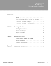
Chapter 1 Operating Instructions Introduction 7 Service 7 General Warnings / Before You Use Your Teknique 8 Hoveround® Teknique / Diagram 12 Hoveround® Teknique / Warning Labels 13 Chapter 1 Operating Instructions 17 Entering Your Teknique 17 Driving Your Teknique 18 Joystick Controllers 20 Chapter 2 Batteries and Charging 22 Caring For Your Batteries and Charger 22 Battery Replacement 23 Charging Your Batteries 24 Chapter 3 Manual Brake Release Levers 27 D82007778 REV N 7/10/12 Table of Contents 5
Chapter 1 Operating Instructions Introduction 7 Service 7 General Warnings / Before You Use Your Teknique 8 Hoveround® Teknique / Diagram 12 Hoveround® Teknique / Warning Labels 13 Chapter 1 Operating Instructions 17 Entering Your Teknique 17 Driving Your Teknique 18 Joystick Controllers 20 Chapter 2 Batteries and Charging 22 Caring For Your Batteries and Charger 22 Battery Replacement 23 Charging Your Batteries 24 Chapter 3 Manual Brake Release Levers 27 D82007778 REV N 7/10/12 Table of Contents 5
User Manual
Page 23
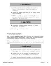
... This will install the correct replacement battery to the supplied wiring diagram located on the battery label. The electrical system may be transported by Hoveround® are classified as specified on the base of your power wheelchair. spill" and may fail and cause severe injury and/or death.... • Do not leave the battery charger connected to replace batteries, consult with EPA regulations. These batteries are of the same type and capacity for this power wheelchair. • ...
... This will install the correct replacement battery to the supplied wiring diagram located on the battery label. The electrical system may be transported by Hoveround® are classified as specified on the base of your power wheelchair. spill" and may fail and cause severe injury and/or death.... • Do not leave the battery charger connected to replace batteries, consult with EPA regulations. These batteries are of the same type and capacity for this power wheelchair. • ...
User Manual
Page 24
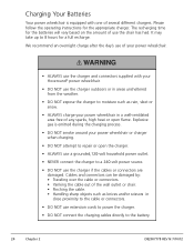
... power outlet. • NEVER connect the charger to a 240-volt power source. • DO NOT use the charger if the cables or connectors are damaged. Explosive gas is equipped with your Hoveround® power wheelchair. • DO NOT use the charger outdoors or in areas unsheltered from the weather.... • DO NOT expose the charger to moisture such as knives and/or scissors in a well-ventilated ...
... power outlet. • NEVER connect the charger to a 240-volt power source. • DO NOT use the charger if the cables or connectors are damaged. Explosive gas is equipped with your Hoveround® power wheelchair. • DO NOT use the charger outdoors or in areas unsheltered from the weather.... • DO NOT expose the charger to moisture such as knives and/or scissors in a well-ventilated ...
User Manual
Page 25
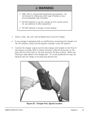
...type of battery or any non-rechargeable type of the joystick controller. Select a clean, dry, cool, well ventilated area to charge a frozen battery. 1. Charger Port, Typical Location D82007778 REV N 7/10/12 Chapter 2 25 • ONLY USE to Figure 2A below. Refer to charge AGM sealed lead acid batteries.... Connect the charger output cord into the charger port located on the port and push the plug in place. Make sure the plug is fully seated in the OFF position. 3. ...
...type of battery or any non-rechargeable type of the joystick controller. Select a clean, dry, cool, well ventilated area to charge a frozen battery. 1. Charger Port, Typical Location D82007778 REV N 7/10/12 Chapter 2 25 • ONLY USE to Figure 2A below. Refer to charge AGM sealed lead acid batteries.... Connect the charger output cord into the charger port located on the port and push the plug in place. Make sure the plug is fully seated in the OFF position. 3. ...
User Manual
Page 26
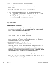
...light is equipped with an on/off button, turn OFF the power switch on AND the cord is working . 2. Switch the power on . If your charger is red, the batteries are being charged. 3. If the light does not go on , please check to make sure the household power is available. Plug... the other end of the charger, indicating power is working . 2. If no lights are charged. 4. When one red and one red light is plugged fully into the controller, the batteries ...
...light is equipped with an on/off button, turn OFF the power switch on AND the cord is working . 2. Switch the power on . If your charger is red, the batteries are being charged. 3. If the light does not go on , please check to make sure the household power is available. Plug... the other end of the charger, indicating power is working . 2. If no lights are charged. 4. When one red and one red light is plugged fully into the controller, the batteries ...

User Manual
Page 44
... ensure that each disables the drive when released. • Check that chair cannot be 45-50 psi.). • Check that casters are tight. • Check charger cords and connectors for instructions.) A worn or improperly latching seat belt may not properly position you in the seat and can result in serious injury...
... ensure that each disables the drive when released. • Check that chair cannot be 45-50 psi.). • Check that casters are tight. • Check charger cords and connectors for instructions.) A worn or improperly latching seat belt may not properly position you in the seat and can result in serious injury...
User Manual
Page 54
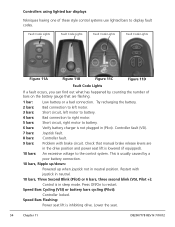
... circuit, left motor to battery. 4 bars: Bad connection to right motor. 5 bars: Short circuit, right motor to battery. 6 bars: Verify battery charger is lowered (if equipped). 10 bars: An excessive voltage to the control system. Check that are in the drive position and power seat lift is...seat lift is usually caused by counting the number of these style control systems use lighted bars to restart. Controllers using lighted bar displays Tekniques having one of bars on the battery gauge that manual brake release levers are flashing. 1 bar: Low battery or a bad connection....
... circuit, left motor to battery. 4 bars: Bad connection to right motor. 5 bars: Short circuit, right motor to battery. 6 bars: Verify battery charger is lowered (if equipped). 10 bars: An excessive voltage to the control system. Check that are in the drive position and power seat lift is...seat lift is usually caused by counting the number of these style control systems use lighted bars to restart. Controllers using lighted bar displays Tekniques having one of bars on the battery gauge that manual brake release levers are flashing. 1 bar: Low battery or a bad connection....

User Manual
Page 55
.... Pilot+ Figure 11G - The chair cannot be removed for the controller on /off the cycling display, press the on your Teknique. To lock the unit, insert and REMOVE the key at the charger port (See Figure 11E and 11F above). D82007778 REV N 7/10/12 Chapter 11 55 If you want to lock...
.... Pilot+ Figure 11G - The chair cannot be removed for the controller on /off the cycling display, press the on your Teknique. To lock the unit, insert and REMOVE the key at the charger port (See Figure 11E and 11F above). D82007778 REV N 7/10/12 Chapter 11 55 If you want to lock...