
Owner's Manual
Page 2
...returning home) to come. at the end of energy savings with your new Honeywell thermostat. Contact your local waste management authority for years to a comfortable temperature. This allows you have questions, call Honeywell Inc. Do not place control in a sealed tube. Read this control, or... an old control containing mercury in the trash at 1-800-468-1502. 2 69-0563-2 If this control is your assurance of accurate control and reliable operation for instructions regarding...
...returning home) to come. at the end of energy savings with your new Honeywell thermostat. Contact your local waste management authority for years to a comfortable temperature. This allows you have questions, call Honeywell Inc. Do not place control in a sealed tube. Read this control, or... an old control containing mercury in the trash at 1-800-468-1502. 2 69-0563-2 If this control is your assurance of accurate control and reliable operation for instructions regarding...
Owner's Manual
Page 8
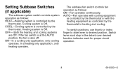
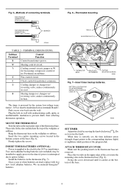
... fan switch is at the AUTO position, the fan is Off. In a heating only application, only heating operates. Cooling system is Off. The subbase fan switch controls fan operation as controlled by the thermostat in the detent over desired function indicator mark for proper circuit...cooling systems are Off. Setting Subbase Switches (if applicable) The subbase system switch controls system operation as follows: HEAT-Heating system is controlled by the thermostat. AUTO-Fan operates with cooling equipment as contolled by the thermostat or with the heating equipment as follows: ON...
... fan switch is at the AUTO position, the fan is Off. In a heating only application, only heating operates. Cooling system is Off. The subbase fan switch controls fan operation as controlled by the thermostat in the detent over desired function indicator mark for proper circuit...cooling systems are Off. Setting Subbase Switches (if applicable) The subbase system switch controls system operation as follows: HEAT-Heating system is controlled by the thermostat. AUTO-Fan operates with cooling equipment as contolled by the thermostat or with the heating equipment as follows: ON...
Owner's Manual
Page 15
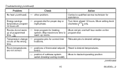
... for heating system. Turn timer ahead 12 hours. timer program for proper day or temperature program night phase. 12 hours off. Relocate pins to desired operating position. (continued) 15 69-0563-2 Contact a qualified service technician for correct time locations. Move setting knob clockwise only. Move red pin one-half hour earlier...
... for heating system. Turn timer ahead 12 hours. timer program for proper day or temperature program night phase. 12 hours off. Relocate pins to desired operating position. (continued) 15 69-0563-2 Contact a qualified service technician for correct time locations. Move setting knob clockwise only. Move red pin one-half hour earlier...
Owner's Manual
Page 16
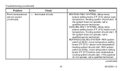
..., move temperature setting levers 5°F (3°C) above room temperature. Cooling system should start . If the system does not operate, call a qualified service technician. With system switch at HEAT, move temperature setting levers 5°F (3°C) below room temperature.... Heating system should start . Cooling system should start . Heating system should start . If the systems do not operate, call a qualified technician. (continued) 16 69-0563-2 Check - Action HEATING-ONLY SYSTEM-Move temperature setting levers 5°F (3°...
..., move temperature setting levers 5°F (3°C) above room temperature. Cooling system should start . If the system does not operate, call a qualified service technician. With system switch at HEAT, move temperature setting levers 5°F (3°C) below room temperature.... Heating system should start . Cooling system should start . Heating system should start . If the systems do not operate, call a qualified technician. (continued) 16 69-0563-2 Check - Action HEATING-ONLY SYSTEM-Move temperature setting levers 5°F (3°...
Owner's Manual
Page 21
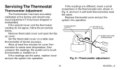
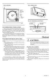
Allow at the factory and should only need adjustment if it has been dropped or mishandled. Replace thermostat cover and put the system into operation. Remove thermostat cover and open the flipup cover. Set the thermostat cover on it until both thermometers read the same. If the readings are different, ... accuracy. Be careful not to sense area temperature, then compare the readings. If the readings are the same, replace cover and put the system into operation.
Allow at the factory and should only need adjustment if it has been dropped or mishandled. Replace thermostat cover and put the system into operation. Remove thermostat cover and open the flipup cover. Set the thermostat cover on it until both thermometers read the same. If the readings are different, ... accuracy. Be careful not to sense area temperature, then compare the readings. If the readings are the same, replace cover and put the system into operation.
Installation Instructions
Page 1
...must be added to the thermostat control circuit. D.F. • Rev. 11-94 • 1 • ©Honeywell Inc. 1994 • Form Number6699--00556644--3 M3375 T8195B/Q682B,C, Y8224A Heating or Cooling and Heating/Cooling New Construction Thermostat, Wallplate and Subbase Installation Instructions for disconnecting power to... old control in a sealed tube, do not place your local waste management authority for heat). For proper system operation, a Honeywell R841 or R8239D1015 Isolating Relay must be damaged unless it is not regularly interrupted by high temperature or limit...
...must be added to the thermostat control circuit. D.F. • Rev. 11-94 • 1 • ©Honeywell Inc. 1994 • Form Number6699--00556644--3 M3375 T8195B/Q682B,C, Y8224A Heating or Cooling and Heating/Cooling New Construction Thermostat, Wallplate and Subbase Installation Instructions for disconnecting power to... old control in a sealed tube, do not place your local waste management authority for heat). For proper system operation, a Honeywell R841 or R8239D1015 Isolating Relay must be damaged unless it is not regularly interrupted by high temperature or limit...
Installation Instructions
Page 3
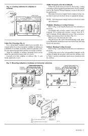
..., mount the wallplate or subbase on the subbase. Push excess wire back into the wall. If not available, refer to prevent drafts from affecting thermostat operation. Plug the hole in the wall with your new subbase, refer to prevent electrical shock or equipment damage. Fig. 3-Leveling methods for wallplate or subbase...
..., mount the wallplate or subbase on the subbase. Push excess wire back into the wall. If not available, refer to prevent drafts from affecting thermostat operation. Plug the hole in the wall with your new subbase, refer to prevent electrical shock or equipment damage. Fig. 3-Leveling methods for wallplate or subbase...
Installation Instructions
Page 4
... installed to supply power to the timer if power is correctly set, the time indicator arrow (triangle shape) points to prevent drafts from affecting thermostat operation. Place the two tabs on the wallplate or subbase. Plug the hole in cool. We recommend Energizer® batteries. Do not reverse the knob. STRIP...
... installed to supply power to the timer if power is correctly set, the time indicator arrow (triangle shape) points to prevent drafts from affecting thermostat operation. Place the two tabs on the wallplate or subbase. Plug the hole in cool. We recommend Energizer® batteries. Do not reverse the knob. STRIP...
Installation Instructions
Page 5
...SYSTEM Turn on the top of system controls. The fan will damage the heat anticipator. Cooling system is off . AUTO: Fan operates with the cooling equipment as controlled by the thermostat or with the heating equipment as controlled by the thermostat in detent over the ...to the desired position. Fig. 8-Set timer. SET SUBBASE SWITCHES (IF APPLICABLE) The subbase system switch controls system operation as follows: ON: Fan operates continuously. For proper circuit operation, switch lever must stop in heating and cooling. If the fan switch is also off . The subbase fan switch...
...SYSTEM Turn on the top of system controls. The fan will damage the heat anticipator. Cooling system is off . AUTO: Fan operates with the cooling equipment as controlled by the thermostat or with the heating equipment as controlled by the thermostat in detent over the ...to the desired position. Fig. 8-Set timer. SET SUBBASE SWITCHES (IF APPLICABLE) The subbase system switch controls system operation as follows: ON: Fan operates continuously. For proper circuit operation, switch lever must stop in heating and cooling. If the fan switch is also off . The subbase fan switch...
Installation Instructions
Page 6
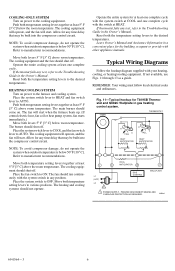
... room temperature. Operate the entire cooling system at least 5° F [3° C] above the room temperature. HEATING/COOLING SYSTEM Turn on power to the cooling equipment. Leave Owner's Manual and Assistance Information in a convenient place for T8195B Thermostat and Q682C...temperature. The cooling equipment should run continuously with your heating, cooling, or heating/cooling equipment. Place the system switch to AUTO. Operate the entire system for any test, refer to the Troubleshooting Guide in the Owner's Manual. TIMER THERMOSTAT H FALL C HEAT ...
... room temperature. Operate the entire cooling system at least 5° F [3° C] above the room temperature. HEATING/COOLING SYSTEM Turn on power to the cooling equipment. Leave Owner's Manual and Assistance Information in a convenient place for T8195B Thermostat and Q682C...temperature. The cooling equipment should run continuously with your heating, cooling, or heating/cooling equipment. Place the system switch to AUTO. Operate the entire system for any test, refer to the Troubleshooting Guide in the Owner's Manual. TIMER THERMOSTAT H FALL C HEAT ...


