
Specifications
Page 6
......35 6.6.1 Sound power levels 35 6.6.2 Discrete tone penalty 35 6.7. Electrical interface specification 39 7.1. 6.3. Multi word DMA timings 46 7.9. Mechanical specifications 30 ...40 7.4. PIO timings...45 7.8. Reset timings ...44 7.7. Electromagnetic compatibility 36 6.8.1 CE mark ...36 6.8.2 C-TICK mark ...36 6.8.3 BSMI mark ...36 6.8.4 MIC mark ...36 6.9. Signal descriptions...41 7.5. Cabling...39 7.2. Ultra DMA timings...47 7.9.1 Initiating Read DMA 47 7.9.2 Host Pausing Read DMA 48 Travelstar 5K100 Hard Disk Drive Specification ii Packaging...37 7.0. Interface...
......35 6.6.1 Sound power levels 35 6.6.2 Discrete tone penalty 35 6.7. Electrical interface specification 39 7.1. 6.3. Multi word DMA timings 46 7.9. Mechanical specifications 30 ...40 7.4. PIO timings...45 7.8. Reset timings ...44 7.7. Electromagnetic compatibility 36 6.8.1 CE mark ...36 6.8.2 C-TICK mark ...36 6.8.3 BSMI mark ...36 6.8.4 MIC mark ...36 6.9. Signal descriptions...41 7.5. Cabling...39 7.2. Ultra DMA timings...47 7.9.1 Initiating Read DMA 47 7.9.2 Host Pausing Read DMA 48 Travelstar 5K100 Hard Disk Drive Specification ii Packaging...37 7.0. Interface...

Specifications
Page 7
...management commands 74 11.6.3 Standby/Sleep command completion time 74 11.6.4 Standby timer ...75 11.6.5 Status ...75 Travelstar 5K100 Hard Disk Drive Specification iii Terminology ...59 9.0. LBA Low Register...67 10.11. General...69 11.1. Introduction...59 8.2. ...Deviations from standard...61 10.0. Device Control Register 65 10.5. LBA Mid Register ...67 10.12. Reset response ...69 11.2. Register initialization...70 11.3. Interface...
...management commands 74 11.6.3 Standby/Sleep command completion time 74 11.6.4 Standby timer ...75 11.6.5 Status ...75 Travelstar 5K100 Hard Disk Drive Specification iii Terminology ...59 9.0. LBA Low Register...67 10.11. General...69 11.1. Introduction...59 8.2. ...Deviations from standard...61 10.0. Device Control Register 65 10.5. LBA Mid Register ...67 10.12. Reset response ...69 11.2. Register initialization...70 11.3. Interface...

Specifications
Page 8
... 77 11.9.4 Threshold exceeded condition 77 11.9.5 S.M.A.R.T. Write Cache function 87 11.15. Execute Device Diagnostic (90h 106 Travelstar 5K100 Hard Disk Drive Specification iv Device Configuration Overlay (B1h 103 13.2.1 DEVICE CONFIGURATION RESTORE (subcommand C0h 103 13.2.2 DEVICE CONFIGURATION FREEZE LOCK ... Active Idle Mode 76 11.7.3 Low Power Idle Mode 76 11.7.4 Transition time ...76 11.8. Command descriptions...97 13.1. Interface Power Management Mode (Slumber and Partial 76 11.9. Address Offset Feature (vendor specific 85 11.12.1 Enable/Disable Address Offset...
... 77 11.9.4 Threshold exceeded condition 77 11.9.5 S.M.A.R.T. Write Cache function 87 11.15. Execute Device Diagnostic (90h 106 Travelstar 5K100 Hard Disk Drive Specification iv Device Configuration Overlay (B1h 103 13.2.1 DEVICE CONFIGURATION RESTORE (subcommand C0h 103 13.2.2 DEVICE CONFIGURATION FREEZE LOCK ... Active Idle Mode 76 11.7.3 Low Power Idle Mode 76 11.7.4 Transition time ...76 11.8. Command descriptions...97 13.1. Interface Power Management Mode (Slumber and Partial 76 11.9. Address Offset Feature (vendor specific 85 11.12.1 Enable/Disable Address Offset...
Specifications
Page 15
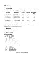
... the specifications of the following Travelstar 5K100, a 2.5-inch hard disk drive, ATA/IDE interface with a rotational speed of 5400 RPM and a height of 9.5 mm: Drive name Model number Travelstar 5K100-100 Travelstar 5K100-80 Travelstar 5K100-60 Travelstar 5K100-40 Travelstar 5K100-30 Travelstar 5K100-20 HTS541010G9AT00 HTS541080G9AT00 HTS541060G9AT00 HTS541040G9AT00 HTS541030G9AT00 HTS541020G9AT00 Capacity 100 GB 80 GB 60 GB 40 GB 30 GB 20 GB Height (mm) Rotation Speed (rpm...
... the specifications of the following Travelstar 5K100, a 2.5-inch hard disk drive, ATA/IDE interface with a rotational speed of 5400 RPM and a height of 9.5 mm: Drive name Model number Travelstar 5K100-100 Travelstar 5K100-80 Travelstar 5K100-60 Travelstar 5K100-40 Travelstar 5K100-30 Travelstar 5K100-20 HTS541010G9AT00 HTS541080G9AT00 HTS541060G9AT00 HTS541040G9AT00 HTS541030G9AT00 HTS541020G9AT00 Capacity 100 GB 80 GB 60 GB 40 GB 30 GB 20 GB Height (mm) Rotation Speed (rpm...

Specifications
Page 17
... V volt VDE Verband Deutscher Electrotechniker W watt 3-state transistor-transistor tristate logic 1.4 Caution • Do not apply force to the drive after its removal from the shipping package and the ESD protective bag are the responsibility of the printed circuit board • This... drive can be damaged by electrostatic discharge (ESD). Any damages incurred to the top cover (See figure below). • Do not cover the breathing hole on the top cover (See figure below). • Do not touch the interface connector pins or the surface of the user. Travelstar 5K100 Hard Disk Drive ...
... V volt VDE Verband Deutscher Electrotechniker W watt 3-state transistor-transistor tristate logic 1.4 Caution • Do not apply force to the drive after its removal from the shipping package and the ESD protective bag are the responsibility of the printed circuit board • This... drive can be damaged by electrostatic discharge (ESD). Any damages incurred to the top cover (See figure below). • Do not cover the breathing hole on the top cover (See figure below). • Do not touch the interface connector pins or the surface of the user. Travelstar 5K100 Hard Disk Drive ...
Specifications
Page 19
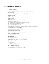
... 100 GB, 80 GB, 60 GB, 40 GB, 30GB, 20 GB • 512 bytes/sector • AT Interface (Enhanced IDE) conforming to ready - 3.5 sec • Operating shock: • 2940 m/sec2 (300 G)/2ms • 1568 m/sec2 (160G)/1ms • Non-operating shock: 9810 m/sec2 (1000 G) 1ms Travelstar 5K100 Hard Disk Drive Specification ...No-ID recording format • Coding : 100/106 • Multi zone recording • Enhanced ECC On-The-Fly • 10 bit 40 symbol non Interleaved Read Solomon code • Non interleave On-The-Fly correction • Included 2 symbol system ECC • Segmented Buffer ...
... 100 GB, 80 GB, 60 GB, 40 GB, 30GB, 20 GB • 512 bytes/sector • AT Interface (Enhanced IDE) conforming to ready - 3.5 sec • Operating shock: • 2940 m/sec2 (300 G)/2ms • 1568 m/sec2 (160G)/1ms • Non-operating shock: 9810 m/sec2 (1000 G) 1ms Travelstar 5K100 Hard Disk Drive Specification ...No-ID recording format • Coding : 100/106 • Multi zone recording • Enhanced ECC On-The-Fly • 10 bit 40 symbol non Interleaved Read Solomon code • Non interleave On-The-Fly correction • Included 2 symbol system ECC • Segmented Buffer ...

Specifications
Page 23
3.0 Fixed-disk subsystem description 3.1 Control electronics The control electronics works with the following functions: • AT Interface Protocol • Embedded Sector Servo • No-ID (TM) formatting • Multizone recording • Code: 100/106 • System ECC ...• Enhanced Adaptive Battery Life Extender 3.2 Head disk assembly data The following technologies are used in the drive: • Pico Slider • Textured laminated AFC glass disk • GMR head • Integrated lead suspension (ILS) • Load/unload mechanism &#...
3.0 Fixed-disk subsystem description 3.1 Control electronics The control electronics works with the following functions: • AT Interface Protocol • Embedded Sector Servo • No-ID (TM) formatting • Multizone recording • Code: 100/106 • System ECC ...• Enhanced Adaptive Battery Life Extender 3.2 Head disk assembly data The following technologies are used in the drive: • Pico Slider • Textured laminated AFC glass disk • GMR head • Integrated lead suspension (ILS) • Load/unload mechanism &#...

Specifications
Page 31
... host interface, are shut off. 4.4.3.2 Mode transition time - The transient timing from Low Power Idle mode to Standby mode is also controlled adaptively, if it is delayed until the spindle becomes ready. Travelstar 5K100 Hard Disk Drive Specification 17 Refer to section 7.10, "Drive address ...setting" on page 55 for details. 4.4.3.4 Adaptive power save control The transient timing from Standby to Idle Table 12: Drive ready time From To Transition Time (typ...
... host interface, are shut off. 4.4.3.2 Mode transition time - The transient timing from Low Power Idle mode to Standby mode is also controlled adaptively, if it is delayed until the spindle becomes ready. Travelstar 5K100 Hard Disk Drive Specification 17 Refer to section 7.10, "Drive address ...setting" on page 55 for details. 4.4.3.4 Adaptive power save control The transient timing from Standby to Idle Table 12: Drive ready time From To Transition Time (typ...
Specifications
Page 41
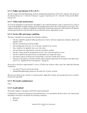
... or voltage level difference between the system frame and power cable ground or AT interface cable ground should comply with the HDA assembly, the drive must be used under the following commands: • Hard reset • Standby Travelstar 5K100 Hard Disk Drive Specification 27 It is controlled by the purchase agreement. 6.3.5 Preventive maintenance None 6.3.6 Load/unload...
... or voltage level difference between the system frame and power cable ground or AT interface cable ground should comply with the HDA assembly, the drive must be used under the following commands: • Hard reset • Standby Travelstar 5K100 Hard Disk Drive Specification 27 It is controlled by the purchase agreement. 6.3.5 Preventive maintenance None 6.3.6 Load/unload...

Specifications
Page 43
Simple power cycling of the system. In this case Hitachi recommends that the power-off portion of the cycle contain the sequence specified in Section 6.3.6.2, "Required Power-Off Sequence" on the disk, therefore this is .... The heads do not land on page 28. Power cycling testing may be viewed as a test of test should be done by commands through the interface, not by power cycling the drive. Travelstar 5K100 Hard Disk Drive Specification 29 Start/Stop testing should be required to test the boot-up function of the...
Simple power cycling of the system. In this case Hitachi recommends that the power-off portion of the cycle contain the sequence specified in Section 6.3.6.2, "Required Power-Off Sequence" on the disk, therefore this is .... The heads do not land on page 28. Power cycling testing may be viewed as a test of test should be done by commands through the interface, not by power cycling the drive. Travelstar 5K100 Hard Disk Drive Specification 29 Start/Stop testing should be required to test the boot-up function of the...

Specifications
Page 45
... hole locations and size of the drive are included in Section 7.2, "Interface connector" on page 55. Thus a drive formatted in Section 7.10, "Drive address setting" on page 39. 6.4.4 Mounting orientation The drive will stay within specification limits if the drive is described in a horizontal orientation ...slave. Connector specifications are shown below. 6.4.3 Connector and jumper description A jumper is 3.0±0.5 kgf-cm. Travelstar 5K100 Hard Disk Drive Specification 31 Performance and error rate will stay within the specified error rates when tilted ±5degrees from ...
... hole locations and size of the drive are included in Section 7.2, "Interface connector" on page 55. Thus a drive formatted in Section 7.10, "Drive address setting" on page 39. 6.4.4 Mounting orientation The drive will stay within specification limits if the drive is described in a horizontal orientation ...slave. Connector specifications are shown below. 6.4.3 Connector and jumper description A jumper is 3.0±0.5 kgf-cm. Travelstar 5K100 Hard Disk Drive Specification 31 Performance and error rate will stay within the specified error rates when tilted ±5degrees from ...
Specifications
Page 53
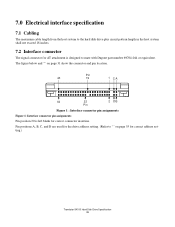
The figure below and "" on page 55 for correct address setting.) Travelstar 5K100 Hard Disk Drive Specification 39 Pin 43 19 1 CA 44 22 2 DB Pin Figure 1 : Interface connector pin assignments Figure 1: Interface connector pin assignments Pin position 20 is designed to "" on page 31 show the ... 69764-044 or equivalent. 7.0 Electrical interface specification 7.1 Cabling The maximum cable length from the host system to the hard disk drive plus circuit pattern length in the host system shall not exceed 18 inches. 7.2 Interface connector The signal connector for AT attachment...
The figure below and "" on page 55 for correct address setting.) Travelstar 5K100 Hard Disk Drive Specification 39 Pin 43 19 1 CA 44 22 2 DB Pin Figure 1 : Interface connector pin assignments Figure 1: Interface connector pin assignments Pin position 20 is designed to "" on page 31 show the ... 69764-044 or equivalent. 7.0 Electrical interface specification 7.1 Cabling The maximum cable length from the host system to the hard disk drive plus circuit pattern length in the host system shall not exceed 18 inches. 7.2 Interface connector The signal connector for AT attachment...
Specifications
Page 54
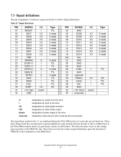
...the termination of the DMA burst. line. I TTL 37 CS0- These lines change upon assertion of interface signals are redefined during the Ultra DMA protocol to their original definitions upon the desertion of DMACK at... the moment the host decides to the drive designates reserved pins which must be left unconnected The signal lines marked with (*) are listed as follows... 3-state 19 GND 21 DMARQ O 3-state 23 DIOW-(*) I TTL 25 DIOR-(*) I /O Type 01 RESET- Travelstar 5K100 Hard Disk Drive Specification 40
...the termination of the DMA burst. line. I TTL 37 CS0- These lines change upon assertion of interface signals are redefined during the Ultra DMA protocol to their original definitions upon the desertion of DMACK at... the moment the host decides to the drive designates reserved pins which must be left unconnected The signal lines marked with (*) are listed as follows... 3-state 19 GND 21 DMARQ O 3-state 23 DIOW-(*) I TTL 25 DIOR-(*) I /O Type 01 RESET- Travelstar 5K100 Hard Disk Drive Specification 40
Specifications
Page 56
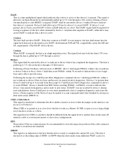
...allow up to avoid master-master or slave-slave configurations. to drive an LED indicator on the same AT interface cable to 5.0 volts through a 10 kΩ resistor. If the host connects to Travelstar 5K100 Hard Disk Drive Specification 42 for any purpose, the host shall ensure that the ...signal level detected on the interface connector is busy and has not yet passed its diagnostics and is present then ...
...allow up to avoid master-master or slave-slave configurations. to drive an LED indicator on the same AT interface cable to 5.0 volts through a 10 kΩ resistor. If the host connects to Travelstar 5K100 Hard Disk Drive Specification 42 for any purpose, the host shall ensure that the ...signal level detected on the interface connector is busy and has not yet passed its diagnostics and is present then ...

Specifications
Page 58
... (µs) - 25 Max (µs) 9.5 - BUSY t10 t1 PARAMETER DESCRIPTION t1 RESET- 7.5 Interface logic signal levels The interface logic signals have the following electrical specifications: Inputs Outputs Current Voltage Input high (ViH) 2.0 V min./5.5 V max. high to Not BUSY t10 RESET- Travelstar 5K100 Hard Disk Drive Specification 44 Voltage output high at IoH min (VoH) Voltage output...
... (µs) - 25 Max (µs) 9.5 - BUSY t10 t1 PARAMETER DESCRIPTION t1 RESET- 7.5 Interface logic signal levels The interface logic signals have the following electrical specifications: Inputs Outputs Current Voltage Input high (ViH) 2.0 V min./5.5 V max. high to Not BUSY t10 RESET- Travelstar 5K100 Hard Disk Drive Specification 44 Voltage output high at IoH min (VoH) Voltage output...

Specifications
Page 69
... shown below. If pin 28 is ground (or low), the drive is a Slave. Travelstar 5K100 Hard Disk Drive Specification 55 When the drive address is Cable Select, the address depends on the interface connector determines the drive address. If pin 28 is open (or logic high), the drive is a Master. Two addresses require the setting of the AT...
... shown below. If pin 28 is ground (or low), the drive is a Slave. Travelstar 5K100 Hard Disk Drive Specification 55 When the drive address is Cable Select, the address depends on the interface connector determines the drive address. If pin 28 is open (or logic high), the drive is a Master. Two addresses require the setting of the AT...

Specifications
Page 71
Interface specification Travelstar 5K100 Hard Disk Drive Specification 57 Part 2.
Interface specification Travelstar 5K100 Hard Disk Drive Specification 57 Part 2.
Specifications
Page 73
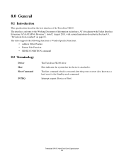
... drive Host indicates the system that the device is attached to the Working Document of the Travelstar 5K100. The first command which is the Standby mode command. Interrupt request (Device or Host) Travelstar 5K100 Hard Disk Drive Specification 59 The drive supports the following functions as a hard reset) is executed after the power on page 61. The interface...
... drive Host indicates the system that the device is attached to the Working Document of the Travelstar 5K100. The first command which is the Standby mode command. Interrupt request (Device or Host) Travelstar 5K100 Hard Disk Drive Specification 59 The drive supports the following functions as a hard reset) is executed after the power on page 61. The interface...

Specifications
Page 75
...exceeded condition unless the prefailure attributes exceed their corresponding thresholds. The interface conforms to the referenced specifications, with the following deviation: Write Verify S.M.A.R.T. The function is the same as WRITE SECTORS command. Travelstar 5K100 Hard Disk Drive Specification 61 For example, a Power-On Hours Attribute never ...Deviations from standard The device conforms to the Working Document of Information Technology, AT Attachment with Packet Interface Extension (ATA/ATAPI-6) Revision 3, dated 30 October 2001, with deviations described below.
...exceeded condition unless the prefailure attributes exceed their corresponding thresholds. The interface conforms to the referenced specifications, with the following deviation: Write Verify S.M.A.R.T. The function is the same as WRITE SECTORS command. Travelstar 5K100 Hard Disk Drive Specification 61 For example, a Power-On Hours Attribute never ...Deviations from standard The device conforms to the Working Document of Information Technology, AT Attachment with Packet Interface Extension (ATA/ATAPI-6) Revision 3, dated 30 October 2001, with deviations described below.

Specifications
Page 80
... 10.8 Features Register This register is in an output register. Bit Definitions ICRCE (CRC) UNC IDNF (IDN) ABRT (ABT) TK0NF (T0N) Interface CRC Error. When CRC = 1, it indicates that a CRC error has occurred on , a reset, or completion of an Execute Device Diagnostic ...5 4 3 2 1 0 CRC UNC 0 IDNF 0 ABRT TK0NF AMNF This register contains the status from the last command executed by CHS mode. Travelstar 5K100 Hard Disk Drive Specification 66 When DRV = 1, device 1 (Slave) is used with the Set Features command, the S.M.A.R.T. At the completion of any command except Execute...
... 10.8 Features Register This register is in an output register. Bit Definitions ICRCE (CRC) UNC IDNF (IDN) ABRT (ABT) TK0NF (T0N) Interface CRC Error. When CRC = 1, it indicates that a CRC error has occurred on , a reset, or completion of an Execute Device Diagnostic ...5 4 3 2 1 0 CRC UNC 0 IDNF 0 ABRT TK0NF AMNF This register contains the status from the last command executed by CHS mode. Travelstar 5K100 Hard Disk Drive Specification 66 When DRV = 1, device 1 (Slave) is used with the Set Features command, the S.M.A.R.T. At the completion of any command except Execute...