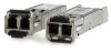
Serial Attached SCSI storage technology, 2nd Edition
Page 2
...understanding the concepts described in 1981 to become an American (ANSI) and international (ISO/IEC) standard. Since that functions as a switch to attach one another by means of a service delivery subsystem SAS drives that provide maximum reliability, highest performance, scalability, and error...interface for non-mission-critical environments A device that time, there have been seven generations of the parallel SCSI protocol. In 2001, HP (Compaq), IBM, LSI Logic, Maxtor, and Seagate founded the Serial Attached SCSI Working Group to come. After the development of ...
Serial Attached SCSI storage technology, 2nd Edition
Page 3
... zoning expander devices that cooperate to control access between a SAS initiator port and a SAS target port A routing technique used for the physical layer of the OSI model. Table routing is used when a device is not able to find other devices in the same subbranch. This will...of targets attached to a different branch altogether. The initiator is a host bus adaptor (HBA), or controller. Expanders are low-cost, high-speed switches that scale the number of physical links that attaches a wide port to another wide port A port that contains more targets-SAS hard disk drives,...
BladeSystem c-Class Solution Overview Setup Poster
Page 7
...Insight Control Management DVD and use the optional integrated DVD-ROM drive to install the operating system. For more information, see the HP BladeSystem c3000 Enclosure Setup and Installation Guide on the HP website (http://www.hp.com/go/bladesystem/documentation). • Use...deploying the management software and creating provisioning policies: • Complete the installation checklist. • Be sure that the HP BladeSystem enclosure, switches, and associated storage resources are discovered and can be managed by the previously installed management system. The RDP software ...
HP BladeSystem c7000 Enclosure Maintenance and Service Guide
Page 3
... ...33 Device bay shelf...33 Half-height or full-height blade ...36 HP BladeSystem Insight Display...38 Fan blank...40 Active Cool 200 fan ...41 Interconnect blank ...41 Interconnect switch or Pass-Thru module ...42 Interconnect bay dividers...43 Onboard Administrator blank ...44...signal pass-thru board ...51 Midplane assembly ...53 Cabling ...55 Single-phase AC configuration ...55 Three-phase AC configuration ...55 HP BladeSystem c7000 Enclosure DC configuration 56 Onboard Administrator cabling ...57 Onboard Administrator with KVM cabling 58 Diagnostic tools ...59 Troubleshooting resources ...
HP BladeSystem c7000 Enclosure Maintenance and Service Guide
Page 23
... Mandatory1 Mandatory1 Mandatory1 Illustrated parts catalog 23 a) HP GbE2c Ethernet Blade Switch for HP c-Class BladeSystem 414037-001 b) HP GbE2c Layer 2/3 Ethernet Blade Switch for c-Class BladeSystem* 438475-001 c) HP 10Gb Ethernet BL-c Switch* 447116-001 d) HP 1:10Gb Ethernet BL-c Switch* 438476-001 e) Brocade 4Gb SAN Switch for HP cClass BladeSystem, 12 ports* f) Brocade 4Gb SAN switch for HP cClass BladeSystem, 24 ports* 411120-001 411121...
HP BladeSystem c7000 Enclosure Maintenance and Service Guide
Page 31
... all power from the server blades or workstation blades, remove the server blades or workstation blades from the Virtual Power menu: - b. The storage blades automatically switch to power down the storage blades In systems that the system power LED is still being provided. IMPORTANT: When the server blades or workstation blades...
HP BladeSystem c7000 Enclosure Maintenance and Service Guide
Page 42
..., do not operate the enclosure for replacement of components, see the appropriate HP BladeSystem c-Class enclosure setup and installation guide. IMPORTANT: An SFP port must be sure that all critical network activity has stopped before removing the interconnect module. 2. Interconnect switch or Pass-Thru module CAUTION: This procedure provides instructions for extended periods...
HP BladeSystem c7000 Enclosure Maintenance and Service Guide
Page 43
Remove the interconnect switch or Pass-Thru module. Removal and replacement procedures 43 Interconnect bay dividers To remove the component: 1. CAUTION: For best cooling practices, do not operate the ... replace the component, reverse the removal procedure. When removing an active component, replace it with more than one component or blank removed. 4. Remove the interconnect switches and Pass-Thru modules ("Interconnect switch or Pass-Thru module" on page 41). 3. Press the release tab.
HP BladeSystem c7000 Enclosure Maintenance and Service Guide
Page 47
... 8 cm (3 in ): o Half-height and full-height blades ("Half-height or full-height blade" on page 36) o Power supplies ("HP BladeSystem c7000 power supply or power supply blank" on page 41). 6. To remove the component: 1. Disengage and extend the following components approximately 8... cables. 4. Remove the Onboard Administrator tray ("Onboard Administrator tray" on page 42). 7. Remove the interconnect switches and Pass-Thru modules ("Interconnect switch or Pass-Thru module" on page 45). 9. a. Remove the Onboard Administrator modules ("Onboard Administrator" on page 31). 3....
HP BladeSystem c7000 Enclosure Maintenance and Service Guide
Page 49
... down the server blades ("Power down the enclosure (on page 45). 11. Remove the power supplies ("HP BladeSystem c7000 power supply or power supply blank" on page 42). 9. Remove the interconnect switches and Pass-Thru modules ("Interconnect switch or Pass-Thru module" on page 32). 7. WARNING: To reduce the risk of damage to...
HP BladeSystem c7000 Enclosure Maintenance and Service Guide
Page 52
...components approximately 8 cm (3 in): o Half-height and full-height blades ("Half-height or full-height blade" on page 36) o Power supplies ("HP BladeSystem c7000 power supply or power supply blank" on page 44). Remove the Onboard Administrator tray ("Onboard Administrator tray" on page 42). 7. Remove the... two T-15 Torx screws that secure the pass-thru board. 10. Remove the interconnect switches and Pass-Thru modules ("Interconnect switch or Pass-Thru module" on page 45). 8. Removal and replacement procedures 52 WARNING: To reduce the risk of personal injury or...
HP BladeSystem c7000 Enclosure Maintenance and Service Guide
Page 53
...blades ("Half-height or full-height blade" on page 36) o Power supplies ("HP BladeSystem c7000 power supply or power supply blank" on page 30). 2. Remove the interconnect switches and Pass-Thru modules ("Interconnect switch or Pass-Thru module" on page 47). 9. Remove the rear cage ("Rear cage...page 41). 6. Remove the Insight Display signal pass-thru board ("Insight Display signal pass-thru board" on accessing the CLI. See the HP BladeSystem Onboard Administrator Command Line Interface User Guide for information on page 51). Power down the server blades or workstation blades" on page ...
HP GbE2c Ethernet Blade Switch for c-Class BladeSystem Application Guide
Page 3
...based configurations ...14 Configuring SNMP trap hosts ...15 SNMPv2 trap host configuration ...16 SNMPv3 trap host configuration ...16 Secure access to the switch ...17 Setting allowable source IP address ranges 17 RADIUS authentication and authorization 18 TACACS+ authentication ...21 How TACACS+ authentication works 22 ... and Secure Copy...25 User access control ...29 Setting up user IDs ...29 Ports and trunking Introduction ...30 Ports on the switch ...30 Port trunk groups...31 Statistical load distribution...31 Built-in fault tolerance ...31 Before you configure trunks ...31 Trunk group...
HP GbE2c Ethernet Blade Switch for c-Class BladeSystem Application Guide
Page 4
... Protocol...65 MSTP region...65 Common Internal Spanning Tree ...65 MSTP configuration guidelines ...65 MSTP configuration example ...65 Quality of Service Introduction ...70 Accessing the switch 4
HP GbE2c Ethernet Blade Switch for c-Class BladeSystem Application Guide
Page 5
... multicast router...98 IGMP Snooping configuration example 98 OSPF OSPF overview ...107 Types of OSPF areas ...107 Types of OSPF routing devices...108 Accessing the switch 5
HP GbE2c Ethernet Blade Switch for c-Class BladeSystem Application Guide
Page 6
......116 Example 1: Simple OSPF domain (CLI example 116 Example 2: Virtual links ...124 Configuring OSPF for a virtual link on Switch B 126 Example 3: Summarizing routes...127 Verifying OSPF configuration...128 Remote monitoring Introduction ...129 Overview...129 RMON group 1-statistics ...129 ...146 Failover methods...146 Active-Active redundancy ...147 GbE2c extensions to VRRP ...147 Tracking VRRP router priority ...147 Virtual router deployment considerations 147 Assigning VRRP virtual router ID ...148 Configuring the switch for tracking ...148 High availability configurations ...148 Active...
HP GbE2c Ethernet Blade Switch for c-Class BladeSystem Application Guide
Page 7
Other network troubleshooting techniques 162 Console and Syslog messages ...162 Ping ...162 Trace route...163 Statistics and state information ...163 Customer support tools ...163 Index Accessing the switch 7
HP GbE2c Ethernet Blade Switch for c-Class BladeSystem Application Guide
Page 8
Layer 3 IP Routing features are available at http://www.hp.com/go/bladesystem/documentation. • HP GbE2c Ethernet Blade Switch for c-Class BladeSystem User Guide • HP GbE2c Ethernet Blade Switch for c-Class BladeSystem Command Reference Guide • HP GbE2c Ethernet Blade Switch for c-Class BladeSystem ISCLI Reference Guide • HP GbE2c Ethernet Blade Switch for c-Class BladeSystem Browser-based Interface Reference Guide • HP GbE2c Ethernet...
HP GbE2c Ethernet Blade Switch for c-Class BladeSystem Application Guide
Page 9
... AaBbCc123 AaBbCc123 [ ] Meaning Example This type depicts onscreen computer output and prompts. host# ls [-a] Management Network The GbE2c is configured to the switch through its internal management port (port 19). The BladeSystem chassis includes an Onboard Administrator as the central element for the ... management VLAN 4095, and no other VLANS are optional and can be used in console port. You can use Rapid Spanning Tree Protocol, STG 1 contains management VLAN 4095. Connect the Onboard administrator and the GbE2c to the network, and disable Enclosure-Based IP Addressing...
HP GbE2c Ethernet Blade Switch for c-Class BladeSystem Application Guide
Page 10
...HP GbE2c Ethernet Blade Switch for users familiar with similar products. Using the command line interfaces The command line interface (CLI) can be accessed via local terminal connection or a remote session using a Telnet connection. Boot Options Menu - An example of the AOS CLI, with the switch... User Guide. For more information, see the "Secure Shell and Secure Copy" section later in order to the switch, see the HP GbE2c Ethernet Blade Switch for a user and an administrator as those available through the console port, minus certain commands. Configuration Menu - Revert...