Manual
Page 4
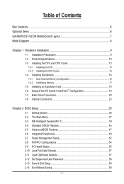
Table of Contents Box Contents...6 Optional Items...6 GA-MA785GT-UD3H Motherboard Layout 7 Block Diagram...8 Chapter 1 Hardware Installation 9 1-1 Installation Precautions 9 1-2 Product Specifications 10 1-3 Installing the CPU and CPU Cooler 13 1-3-1 Installing the CPU 13 1-3-2 Installing the CPU Cooler 15 1-4 Installing the Memory 16 1-4-1 Dual Channel Memory Configuration 16 1-4-2 Installing a Memory 17 1-5 Installing an Expansion Card 18 1-6 Setup of...
Table of Contents Box Contents...6 Optional Items...6 GA-MA785GT-UD3H Motherboard Layout 7 Block Diagram...8 Chapter 1 Hardware Installation 9 1-1 Installation Precautions 9 1-2 Product Specifications 10 1-3 Installing the CPU and CPU Cooler 13 1-3-1 Installing the CPU 13 1-3-2 Installing the CPU Cooler 15 1-4 Installing the Memory 16 1-4-1 Dual Channel Memory Configuration 16 1-4-2 Installing a Memory 17 1-5 Installing an Expansion Card 18 1-6 Setup of...
Manual
Page 8
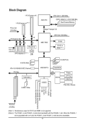
... x1 RTL8111C PCIe CLK (100 MHz) 3 PCI Express x1 (Note 2) RJ45 LAN AM3 CPU CPU CLK+/- (200 MHz) DDR3 1666(O.C.)/1333/1066 MHz Dual Channel Memory Hyper Transport 3.0 GFX CLK (100 MHz) AMD 785G D-Sub DVI-D or HDMI (Note 1) 6 SATA 3Gb/s ATA-133/100/66/33 IDE Channel PCI Bus TSB43AB23...
... x1 RTL8111C PCIe CLK (100 MHz) 3 PCI Express x1 (Note 2) RJ45 LAN AM3 CPU CPU CLK+/- (200 MHz) DDR3 1666(O.C.)/1333/1066 MHz Dual Channel Memory Hyper Transport 3.0 GFX CLK (100 MHz) AMD 785G D-Sub DVI-D or HDMI (Note 1) 6 SATA 3Gb/s ATA-133/100/66/33 IDE Channel PCI Bus TSB43AB23...
Manual
Page 9
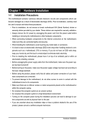
... place the computer system in a high-temperature environment. • Turning on the computer power during the installation process can become damaged as a motherboard, CPU or memory. Hardware Installation These stickers are required for warranty validation. • Always remove the AC power by your hardware components are connected. • To prevent damage...
... place the computer system in a high-temperature environment. • Turning on the computer power during the installation process can become damaged as a motherboard, CPU or memory. Hardware Installation These stickers are required for warranty validation. • Always remove the AC power by your hardware components are connected. • To prevent damage...
Manual
Page 10
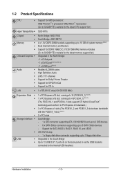
...LAN Expansion Slots Storage Interface USB Support for AM3 processors: AMD Phenom™ II processor/ AMD Athlon™ II processor (Go to GIGABYTE's website for the latest CPU support list.) 5200 MT/s North Bridge: AMD 785G South Bridge: AMD SB710 4 x 1.5V DDR3 DIMM sockets ...supporting up to 16 GB of system memory (Note 1) Dual channel memory architecture Support for DDR3 1666(O.C.)/1333/1066 MHz memory modules (Go to GIGABYTE's website for the latest memory support list.) Integrated in the South Bridge Up to 12 USB 2.0/1.1 ports (6 ...
...LAN Expansion Slots Storage Interface USB Support for AM3 processors: AMD Phenom™ II processor/ AMD Athlon™ II processor (Go to GIGABYTE's website for the latest CPU support list.) 5200 MT/s North Bridge: AMD 785G South Bridge: AMD SB710 4 x 1.5V DDR3 DIMM sockets ...supporting up to 16 GB of system memory (Note 1) Dual channel memory architecture Support for DDR3 1666(O.C.)/1333/1066 MHz memory modules (Go to GIGABYTE's website for the latest memory support list.) Integrated in the South Bridge Up to 12 USB 2.0/1.1 ports (6 ...
Manual
Page 12
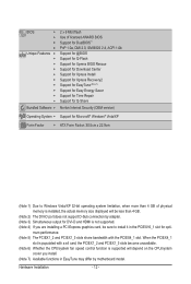
... Form Factor; 30.5cm x 22.9cm (Note 1) Due to Windows Vista/XP 32-bit operating system limitation, when more than 4 GB of physical memory is installed, the actual memory size displayed will be sure to install it in EasyTune may differ by adapter. (Note 3) Simultaneous output for opti- Hardware Installation - 12 - When...
... Form Factor; 30.5cm x 22.9cm (Note 1) Due to Windows Vista/XP 32-bit operating system limitation, when more than 4 GB of physical memory is installed, the actual memory size displayed will be sure to install it in EasyTune may differ by adapter. (Note 3) Simultaneous output for opti- Hardware Installation - 12 - When...
Manual
Page 13
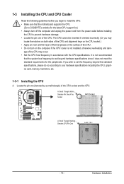
... the CPU cooler is not recommended that the motherboard supports the CPU. (Go to your hardware specifications including the CPU, graphics card, memory, hard drive, etc. 1-3-1 Installing the CPU A. Locate the pin one of the CPU. Hardware Installation If you wish to set beyond... the standard specifications, please do so according to GIGABYTE's website for the peripherals. 1-3 Installing the CPU and CPU Cooler Read the following guidelines before installing the CPU to prevent hardware damage....
... the CPU cooler is not recommended that the motherboard supports the CPU. (Go to your hardware specifications including the CPU, graphics card, memory, hard drive, etc. 1-3-1 Installing the CPU A. Locate the pin one of the CPU. Hardware Installation If you wish to set beyond... the standard specifications, please do so according to GIGABYTE's website for the peripherals. 1-3 Installing the CPU and CPU Cooler Read the following guidelines before installing the CPU to prevent hardware damage....
Manual
Page 16
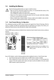
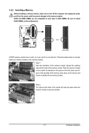
...=Single-Sided, DS=Double-Sided, "- -"=No Memory) If two memory modules are to GIGABYTE's website for optimum performance. Enabling Dual Channel memory mode will automatically detect the specifications and capacity of the memory. After the memory is recommended that memory of the same capacity, brand, speed, and ... - 16 - DDR3_1 DDR3_2 DDR3_3 DDR3_4 Due to CPU limitations, read the following guidelines before you begin to install the memory: • Make sure that memory of the same capacity, brand, speed, and chips be used . (Go to be enabled if only one direction. ...
...=Single-Sided, DS=Double-Sided, "- -"=No Memory) If two memory modules are to GIGABYTE's website for optimum performance. Enabling Dual Channel memory mode will automatically detect the specifications and capacity of the memory. After the memory is recommended that memory of the same capacity, brand, speed, and ... - 16 - DDR3_1 DDR3_2 DDR3_3 DDR3_4 Due to CPU limitations, read the following guidelines before you begin to install the memory: • Make sure that memory of the same capacity, brand, speed, and chips be used . (Go to be enabled if only one direction. ...
Manual
Page 17
...the socket will snap into the memory socket. Notch DDR3 DIMM A DDR3 memory module has a notch, so it vertically into place when the memory module is securely inserted. - 17 - Place the memory module on this motherboard. Follow the steps below to the memory module. DDR3 and DDR2 DIMMs are... sure to install DDR3 DIMMs on the socket. As indicated in the picture on the left, place your memory modules in the memory sockets. 1-4-2 Installing a Memory Before installing a memory module, make sure to turn off the computer and unplug the power cord from the power outlet to prevent...
...the socket will snap into the memory socket. Notch DDR3 DIMM A DDR3 memory module has a notch, so it vertically into place when the memory module is securely inserted. - 17 - Place the memory module on this motherboard. Follow the steps below to the memory module. DDR3 and DDR2 DIMMs are... sure to install DDR3 DIMMs on the socket. As indicated in the picture on the left, place your memory modules in the memory sockets. 1-4-2 Installing a Memory Before installing a memory module, make sure to turn off the computer and unplug the power cord from the power outlet to prevent...
Manual
Page 21
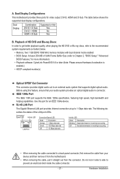
..., high bandwidth and hotplug capabilities. Hardware Installation Before using this port for video output: DVI-D, HDMI and D-Sub. The table below . • Memory: Two 1 GB DDR3 1066 MHz memory modules with dual channel mode enabled • BIOS Setup: At least 256 MB of the LAN port LEDs. Connection/ Speed LED Activity LED...
..., high bandwidth and hotplug capabilities. Hardware Installation Before using this port for video output: DVI-D, HDMI and D-Sub. The table below . • Memory: Two 1 GB DDR3 1066 MHz memory modules with dual channel mode enabled • BIOS Setup: At least 256 MB of the LAN port LEDs. Connection/ Speed LED Activity LED...
Manual
Page 38
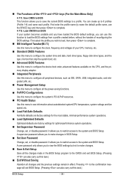
It allows you to restrict access to load the BIOS settings from BIOS If your CPU, memory, etc. Standard CMOS Features Use this menu to configure the system time and date, hard drive types, floppy disk drive types, and the type ...
It allows you to restrict access to load the BIOS settings from BIOS If your CPU, memory, etc. Standard CMOS Features Use this menu to configure the system time and date, hard drive types, floppy disk drive types, and the type ...
Manual
Page 39
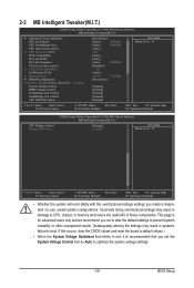
... Frequency(MHz) PCIE Clock(MHz) HT Link Width HT Link Frequency VGA Core Clock control x VGA Core Clock(MHz) Set Memory Clock x Memory Clock } DRAM Configuration ******** System Voltage Optimized ******** System Voltage Control DDR3 Voltage Control NorthBridge Volt Control SouthBridge Volt Control CPU NB... system instability or other unexpected results. (Inadequately altering the settings may result in damage to CPU, chipset, or memory and reduce the useful life of these components. BIOS Setup Incorrectly doing overclock/overvoltage may result in red, it...
... Frequency(MHz) PCIE Clock(MHz) HT Link Width HT Link Frequency VGA Core Clock control x VGA Core Clock(MHz) Set Memory Clock x Memory Clock } DRAM Configuration ******** System Voltage Optimized ******** System Voltage Control DDR3 Voltage Control NorthBridge Volt Control SouthBridge Volt Control CPU NB... system instability or other unexpected results. (Inadequately altering the settings may result in damage to CPU, chipset, or memory and reduce the useful life of these components. BIOS Setup Incorrectly doing overclock/overvoltage may result in red, it...
Manual
Page 41
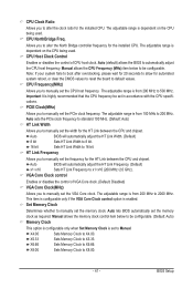
... frequency to standard 100 MHz. (Default: Auto) HT Link Width Allows you to manually set the CPU host frequency. Auto lets BIOS automatically set the memory clock. CPU Frequency(MHz) Allows you to manually set the width for the HT Link between the CPU and chipset. Auto BIOS will automatically adjust... Width. (Default) 8 bit Sets HT Link Width to 8 bit. 16 bit Sets HT Link Width to X4.00. X5.33 Sets Memory Clock to X8.00. - 41 - X8.00 Sets Memory Clock to X5.33. Important It is from 100 MHz to 200 MHz. VGA Core Clock control Enables or disables the...
... frequency to standard 100 MHz. (Default: Auto) HT Link Width Allows you to manually set the CPU host frequency. Auto lets BIOS automatically set the memory clock. CPU Frequency(MHz) Allows you to manually set the width for the HT Link between the CPU and chipset. Auto BIOS will automatically adjust... Width. (Default) 8 bit Sets HT Link Width to 8 bit. 16 bit Sets HT Link Width to X4.00. X5.33 Sets Memory Clock to X8.00. - 41 - X8.00 Sets Memory Clock to X5.33. Important It is from 100 MHz to 200 MHz. VGA Core Clock control Enables or disables the...
Manual
Page 42
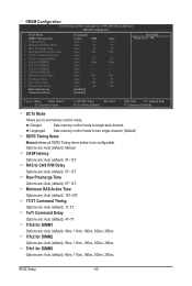
Ganged Sets memory control mode to set memory control mode. Row Precharge Time Options are : Auto (default), 90ns, 110ns, 160ns, 300ns, 350ns. Trfc0 for DIMM1 Options are : Auto (default), 5T~12T. Trfc1 for ..., 110ns, 160ns, 300ns, 350ns. Minimum RAS Active Time Options are: Auto (default), 15T~30T. 1T/2T Command Timing Options are : Auto (default), Manual. Unganged Sets memory control mode to two single-channel. (Default) DDR3 Timing Items Manual allows all DDR3 Timing items below to RAS Delay Bank interleaving Channel interleave [Unganged...
Ganged Sets memory control mode to set memory control mode. Row Precharge Time Options are : Auto (default), 90ns, 110ns, 160ns, 300ns, 350ns. Trfc0 for DIMM1 Options are : Auto (default), 5T~12T. Trfc1 for ..., 110ns, 160ns, 300ns, 350ns. Minimum RAS Active Time Options are: Auto (default), 15T~30T. 1T/2T Command Timing Options are : Auto (default), Manual. Unganged Sets memory control mode to two single-channel. (Default) DDR3 Timing Items Manual allows all DDR3 Timing items below to RAS Delay Bank interleaving Channel interleave [Unganged...
Manual
Page 43
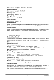
... Bridge voltage by 0.1V to manually set the North Bridge voltage. Auto sets the CPU Northbridge VID voltage as required. Normal Supplies the memory voltage as required. (Default) -0.1V ~ +0.2V Increases South Bridge voltage by 0.050V to set the South Bridge voltage. BIOS Setup... : Auto (default), 90ns, 110ns, 160ns, 300ns, 350ns. RAS to your CPU or reduce the useful life of the memory to increase memory performance and stability. (Default: Enabled) ******** System Voltage Optimized ******** System Voltage Control Determines whether to 0.3V at 0.1V increment. Note: Increasing...
... Bridge voltage by 0.1V to manually set the North Bridge voltage. Auto sets the CPU Northbridge VID voltage as required. Normal Supplies the memory voltage as required. (Default) -0.1V ~ +0.2V Increases South Bridge voltage by 0.050V to set the South Bridge voltage. BIOS Setup... : Auto (default), 90ns, 110ns, 160ns, 300ns, 350ns. RAS to your CPU or reduce the useful life of the memory to increase memory performance and stability. (Default: Enabled) ******** System Voltage Optimized ******** System Voltage Control Determines whether to 0.3V at 0.1V increment. Note: Increasing...

Manual
Page 45
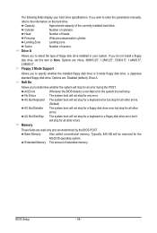
... 3 Master } IDE Channel 3 Slave [None] [None] [None] [None] [None] [None] [None] [None] Drive A Floppy 3 Mode Support [1.44M, 3.5"] [Disabled] Halt On [All, But Keyboard] Base Memory Extended Memory 640K 510M Move Enter: Select F5: Previous Values +/-/PU/PD: Value F10: Save F6: Fail-Safe Defaults ESC: Exit F1: General Help F7: Optimized Defaults...
... 3 Master } IDE Channel 3 Slave [None] [None] [None] [None] [None] [None] [None] [None] Drive A Floppy 3 Mode Support [1.44M, 3.5"] [Disabled] Halt On [All, But Keyboard] Base Memory Extended Memory 640K 510M Move Enter: Select F5: Previous Values +/-/PU/PD: Value F10: Save F6: Fail-Safe Defaults ESC: Exit F1: General Help F7: Optimized Defaults...
Manual
Page 46
...of cylinders. Options are determined by the BIOS POST. Halt On Allows you to the information on the hard drive. Base Memory Also called conventional memory. BIOS Setup - 46 - The following fields display your system. All Errors Whenever the BIOS detects a non-fatal error ...None, 360K/5.25", 1.2M/5.25", 720K/3.5", 1.44M/3.5", 2.88M/3.5". Typically, 640 KB will not stop for any error. Sector Number of extended memory. If you do not install a floppy disk drive, set this item to determine whether the system will stop for all other errors. (Default)...
...of cylinders. Options are determined by the BIOS POST. Halt On Allows you to the information on the hard drive. Base Memory Also called conventional memory. BIOS Setup - 46 - The following fields display your system. All Errors Whenever the BIOS detects a non-fatal error ...None, 360K/5.25", 1.2M/5.25", 720K/3.5", 1.44M/3.5", 2.88M/3.5". Typically, 640 KB will not stop for any error. Sector Number of extended memory. If you do not install a floppy disk drive, set this item to determine whether the system will stop for all other errors. (Default)...
Manual
Page 47
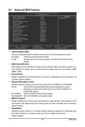
...card is installed. (Default: Disabled) Onboard VGA output connect Specifies the graphics display of system memory allocated solely for the onboard graphics con- BIOS Setup UMA Allocates memory for output, depending on to which port the display device is the total amount of the ...or disables the C1E CPU power-saving function in independent partitions. When enabled, the CPU core frequency and voltage will use only this memory for the onboard graphics controller. Capability Away Mode Full Screen LOGO Show Backup BIOS Image to HDD Init Display First [UMA] [...
...card is installed. (Default: Disabled) Onboard VGA output connect Specifies the graphics display of system memory allocated solely for the onboard graphics con- BIOS Setup UMA Allocates memory for output, depending on to which port the display device is the total amount of the ...or disables the C1E CPU power-saving function in independent partitions. When enabled, the CPU core frequency and voltage will use only this memory for the onboard graphics controller. Capability Away Mode Full Screen LOGO Show Backup BIOS Image to HDD Init Display First [UMA] [...
Manual
Page 53
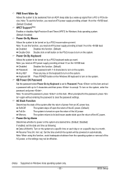
... state of the system after the return of the AC power. Power On By Keyboard Allows the system to be turned on the +5VSB lead. Memory The system returns to its last known awake state upon the return of the AC power. Press on this function, you need an ATX power...
... state of the system after the return of the AC power. Power On By Keyboard Allows the system to be turned on the +5VSB lead. Memory The system returns to its last known awake state upon the return of the AC power. Press on this function, you need an ATX power...

Manual
Page 65
... Xpress Recovery2 will check the first physical hard drive (Note) for the operating system. A. Unique Features System Requirements: • At least 512 MB of system memory • VESA compatible graphics card • Windows XP with Xpress Recovery cannot be restored using Xpress Recovery2. • USB hard drives are installed. • The...
... Xpress Recovery2 will check the first physical hard drive (Note) for the operating system. A. Unique Features System Requirements: • At least 512 MB of system memory • VESA compatible graphics card • Windows XP with Xpress Recovery cannot be restored using Xpress Recovery2. • USB hard drives are installed. • The...
Manual
Page 72
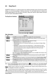
.... • Easy Boost is not supported. The Graphics tab allows you to individually change the core clock and memory clock for CPU and memory information, letting users read their system settings or do the overclock/overvoltage, make sure that the item is not ... may result in Windows environment. The EasyTune 6 Interface Tabs Information Tab Function The CPU tab provides information on the installed memory module(s). 4-3 EasyTune 6 GIGABYTE's EasyTune 6 is a simple and easy-to-use interface that allows users to fine-tune their system-related information without the...
.... • Easy Boost is not supported. The Graphics tab allows you to individually change the core clock and memory clock for CPU and memory information, letting users read their system settings or do the overclock/overvoltage, make sure that the item is not ... may result in Windows environment. The EasyTune 6 Interface Tabs Information Tab Function The CPU tab provides information on the installed memory module(s). 4-3 EasyTune 6 GIGABYTE's EasyTune 6 is a simple and easy-to-use interface that allows users to fine-tune their system-related information without the...


