
Manual
Page 4
Table of Contents ItemChecklist ...6 OptionalAccessories ...6 GA-M59SLI-S5 Motherboard Layout 7 GA-M59SLI-S4 Motherboard Layout 8 Block Diagram ...9 Chapter 1 Hardware Installation 11 1-1 Considerations Prior to Installation 11 1-2 Feature Summary 12 1-3 Installation of the CPU and CPU Cooler 15 1-3-1 Installation of the CPU 15 1-3-2 Installation of the CPU Cooler 16 1-4 Installation of Memory 17 1-5 Installation of Expansion Cards 19 1-6 Setup of SLI...
Table of Contents ItemChecklist ...6 OptionalAccessories ...6 GA-M59SLI-S5 Motherboard Layout 7 GA-M59SLI-S4 Motherboard Layout 8 Block Diagram ...9 Chapter 1 Hardware Installation 11 1-1 Considerations Prior to Installation 11 1-2 Feature Summary 12 1-3 Installation of the CPU and CPU Cooler 15 1-3-1 Installation of the CPU 15 1-3-2 Installation of the CPU Cooler 16 1-4 Installation of Memory 17 1-5 Installation of Expansion Cards 19 1-6 Setup of SLI...
Manual
Page 9
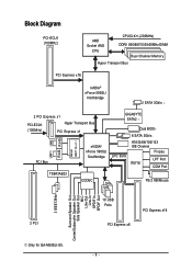
Block Diagram PCI-ECLK (100MHz) AMD Socket AM2 CPU CPUCLK+/-(200MHz) DDRII 800/667/533/400MHz DIMM Dual Channel Memory Hyper Transport Bus PCI Express x16 nVIDIA® nForce 590SLI ...(100MHz) Hyper Transport Bus PCI Express x1 LAN1 LAN2 RJ45 RJ45 Marvell 88E1116 x 2 PCI Bus TSB43AB23 nVIDIA® nForce 590SLI Southbridge CODEC GIGABYTE SATA2 LPC BUS Dual BIOS 6 SATA 3Gb/s ATA33/66/100/133 IDE Channel Floppy IT8716 LPT Port COM Port PS/2 KB/Mouse 2 ... Speaker Out Center/Subwoofer Speaker Out Side Speaker Out MIC Line-Out Line-In SPDIF In SPDIF Out Only for GA-M59SLI-S5. - 9 -
Block Diagram PCI-ECLK (100MHz) AMD Socket AM2 CPU CPUCLK+/-(200MHz) DDRII 800/667/533/400MHz DIMM Dual Channel Memory Hyper Transport Bus PCI Express x16 nVIDIA® nForce 590SLI ...(100MHz) Hyper Transport Bus PCI Express x1 LAN1 LAN2 RJ45 RJ45 Marvell 88E1116 x 2 PCI Bus TSB43AB23 nVIDIA® nForce 590SLI Southbridge CODEC GIGABYTE SATA2 LPC BUS Dual BIOS 6 SATA 3Gb/s ATA33/66/100/133 IDE Channel Floppy IT8716 LPT Port COM Port PS/2 KB/Mouse 2 ... Speaker Out Center/Subwoofer Speaker Out Side Speaker Out MIC Line-Out Line-In SPDIF In SPDIF Out Only for GA-M59SLI-S5. - 9 -
Manual
Page 11
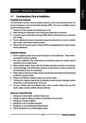
...3. To prevent damage to the motherboard, please do not remove the stickers on the motherboard. Damage due to be an unofficial Gigabyte product. - 11 - Product determined to use exceeding the permitted parameters. 6. Please turn off before unplugging the power supply connector...using the product, please verify that the power supply is best to wear an electrostatic discharge (ESD) cuff when handling electronic components (CPU, RAM). 4. If you are required for warranty validation. 2. Instances of violating the conditions recommended in contact with the motherboard circuit ...
...3. To prevent damage to the motherboard, please do not remove the stickers on the motherboard. Damage due to be an unofficial Gigabyte product. - 11 - Product determined to use exceeding the permitted parameters. 6. Please turn off before unplugging the power supply connector...using the product, please verify that the power supply is best to wear an electrostatic discharge (ESD) cuff when handling electronic components (CPU, RAM). 4. If you are required for warranty validation. 2. Instances of violating the conditions recommended in contact with the motherboard circuit ...
Manual
Page 12
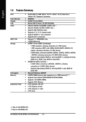
... 3Gb/s connectors (SATAII0, SATAII1, SATAII2, SATAII3, SATAII4 , SATAII5), allowing connection of 2 SATA 3Gb/s devices - GA-M59SLI-S5/GA-M59SLI-S4 Motherboard - 12 - Only for GA-M59SLI-S5. Supports data striping (RAID 0), mirroring (RAID 1) and JBOD for Serial ATA Š Microsoft Windows 2000/XP Š...Supports CD In connection Š Onboard T.I. English 1-2 Feature Summary CPU Front Side Bus Chipset LAN Audio IEEE 1394 Storage O.S Support Memory Expanstion Slots Š Socket AM2 for Serial ATA Š GIGABYTE SATA2 Controller - 2 SATA 3Gb/s connectors (JSATAII0, JSATAII1), allowing...
... 3Gb/s connectors (SATAII0, SATAII1, SATAII2, SATAII3, SATAII4 , SATAII5), allowing connection of 2 SATA 3Gb/s devices - GA-M59SLI-S5/GA-M59SLI-S4 Motherboard - 12 - Only for GA-M59SLI-S5. Supports data striping (RAID 0), mirroring (RAID 1) and JBOD for Serial ATA Š Microsoft Windows 2000/XP Š...Supports CD In connection Š Onboard T.I. English 1-2 Feature Summary CPU Front Side Bus Chipset LAN Audio IEEE 1394 Storage O.S Support Memory Expanstion Slots Š Socket AM2 for Serial ATA Š GIGABYTE SATA2 Controller - 2 SATA 3Gb/s connectors (JSATAII0, JSATAII1), allowing...
Manual
Page 13
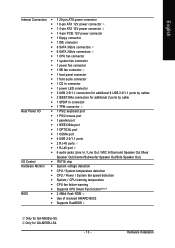
... 1 floppy connector Š 1 IDE connector Š 8 SATA 3Gb/s connectors Š 6 SATA 3Gb/s connectors Š 1 CPU fan connector Š 1 system fan connector Š 1 power fan connector Š 1 SB fan connector Š 1 front panel...CPU / System temperature detection Š CPU / Power / System fan speed detection Š System / CPU warning temperature Š CPU fan failure warning Š Supports CPU Smart Fan function(Note 2) BIOS Š 2 4Mbit flash ROM Š Use of licensed AWARD BIOS Š Supports DualBIOS Only for GA-M59SLI-S4. - 13 - Only for GA-M59SLI-S5...
... 1 floppy connector Š 1 IDE connector Š 8 SATA 3Gb/s connectors Š 6 SATA 3Gb/s connectors Š 1 CPU fan connector Š 1 system fan connector Š 1 power fan connector Š 1 SB fan connector Š 1 front panel...CPU / System temperature detection Š CPU / Power / System fan speed detection Š System / CPU warning temperature Š CPU fan failure warning Š Supports CPU Smart Fan function(Note 2) BIOS Š 2 4Mbit flash ROM Š Use of licensed AWARD BIOS Š Supports DualBIOS Only for GA-M59SLI-S4. - 13 - Only for GA-M59SLI-S5...
Manual
Page 14
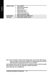
... FAN Control function is installed, the actual memory available for the operating system will depend on the CPU you install. (Note 3) EasyTune functions may vary depending on different motherboards. (Note 4) Silent Pipe only for GA-M59SLI-S5. English Additional Features Š Supports @BIOS Š Supports Download Center Š Supports Q-Flash Š Supports EasyTune(Note...
... FAN Control function is installed, the actual memory available for the operating system will depend on the CPU you install. (Note 3) EasyTune functions may vary depending on different motherboards. (Note 4) Silent Pipe only for GA-M59SLI-S5. English Additional Features Š Supports @BIOS Š Supports Download Center Š Supports Q-Flash Š Supports EasyTune(Note...
Manual
Page 15
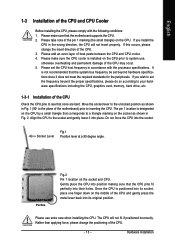
... to the plane of the pin 1 marking (the small triangle) on the socket as shown in Fig. 2. Do not force the CPU into their holes. The pin 1 location is not recommended that the system bus frequency be set the frequency beyond hardware specifications since it into...place. Please use , otherwise overheating and permanent damage of the CPU Check the CPU pins to your hardware specifications including the CPU, graphics card, memory, hard drive, etc. 1-3-1 Installation of the CPU may occur. 5. Please make sure the CPU cooler is positioned into its socket, place one finger down on...
... to the plane of the pin 1 marking (the small triangle) on the socket as shown in Fig. 2. Do not force the CPU into their holes. The pin 1 location is not recommended that the system bus frequency be set the frequency beyond hardware specifications since it into...place. Please use , otherwise overheating and permanent damage of the CPU Check the CPU pins to your hardware specifications including the CPU, graphics card, memory, hard drive, etc. 1-3-1 Installation of the CPU may occur. 5. Please make sure the CPU cooler is positioned into its socket, place one finger down on...

Manual
Page 16
...GA-M59SLI-S5/GA-M59SLI-S4 Motherboard - 16 - English 1-3-2 Installation of the CPU Cooler Fig.1 Before installing the CPU cooler, please first add an even layer of heat paste on the motherboard so that either thermal tape rather than heat paste be used for detailed installation instructions). The CPU cooler may adhere to the CPU... as a result of hardening of the CPU. Install all the CPU cooler components (Please refer to prevent CPU overheating. To prevent such an occurrence, it is suggested that the CPU cooler can properly...
...GA-M59SLI-S5/GA-M59SLI-S4 Motherboard - 16 - English 1-3-2 Installation of the CPU Cooler Fig.1 Before installing the CPU cooler, please first add an even layer of heat paste on the motherboard so that either thermal tape rather than heat paste be used for detailed installation instructions). The CPU cooler may adhere to the CPU... as a result of hardening of the CPU. Install all the CPU cooler components (Please refer to prevent CPU overheating. To prevent such an occurrence, it is suggested that the CPU cooler can properly...

Manual
Page 18
...The following is recommended to use memory modules of the same color. 3. DS/SS DDRII2 DS/SS - GA-M59SLI-S5/GA-M59SLI-S4 Motherboard - 18 - English Dual Channel Memory Configuration The GA-M59SLI-S5/GA-M59SLI-S4 supports the Dual Channel Technology. DS/SS DS/SS DDRII4 - DS/SS DS/SS If two ... SS: Single Side, "--": Empty) DIMM Socket 2 memory modules 4 memory modules DDRII1 DS/SS - Dual Channel mode will double. Due to CPU limitation, if you wish to achieve Dual Channel mode, we recommend installing them into DIMM sockets of identical brand, size, chips, and speed),...
...The following is recommended to use memory modules of the same color. 3. DS/SS DDRII2 DS/SS - GA-M59SLI-S5/GA-M59SLI-S4 Motherboard - 18 - English Dual Channel Memory Configuration The GA-M59SLI-S5/GA-M59SLI-S4 supports the Dual Channel Technology. DS/SS DS/SS DDRII4 - DS/SS DS/SS If two ... SS: Single Side, "--": Empty) DIMM Socket 2 memory modules 4 memory modules DDRII1 DS/SS - Dual Channel mode will double. Due to CPU limitation, if you wish to achieve Dual Channel mode, we recommend installing them into DIMM sockets of identical brand, size, chips, and speed),...
Manual
Page 25
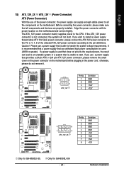
...ATX 12V power connector, please remove the small cover on the power connector on the motherboard and connect tightly. Only for GA-M59SLI-S5. Caution! If the ATX_12V power connector is not connected, the system will not start . The ATX_12V power connector mainly ...No. 1 2 3 4 Definition GND GND +12V +12V 5 8 1 4 ATX_12V_2X Pin No. 1 2 3 4 5 6 7 8 Definition GND GND GND GND +12V +12V +12V +12V Only for GA-M59SLI-S4. - 25 - Before connecting the power connector, please make sure that can lead to an unstable system or a system that is recommended that a power supply...
...ATX 12V power connector, please remove the small cover on the power connector on the motherboard and connect tightly. Only for GA-M59SLI-S5. Caution! If the ATX_12V power connector is not connected, the system will not start . The ATX_12V power connector mainly ...No. 1 2 3 4 Definition GND GND +12V +12V 5 8 1 4 ATX_12V_2X Pin No. 1 2 3 4 5 6 7 8 Definition GND GND GND GND +12V +12V +12V +12V Only for GA-M59SLI-S4. - 25 - Before connecting the power connector, please make sure that can lead to an unstable system or a system that is recommended that a power supply...

Manual
Page 27
...via a 3-pin/4-pin (only for CPU_FAN) - 27 - The black connector wire is the ground wire (GND). Remember to connect the CPU/system fan cable to the CPU_FAN/SYS_FAN connector to the PCIE x16 slot. English 3) PCIE_12V (Power Connector) The PCIE_12V power connector supplies extra ...power to prevent CPU damage or system hanging caused by overheating. 1 CPU_FAN 1 SYS_FAN/PWR_FAN Pin No. 1 2 3 4 Definition GND +12V Sense Speed Control (...
...via a 3-pin/4-pin (only for CPU_FAN) - 27 - The black connector wire is the ground wire (GND). Remember to connect the CPU/system fan cable to the CPU_FAN/SYS_FAN connector to the PCIE x16 slot. English 3) PCIE_12V (Power Connector) The PCIE_12V power connector supplies extra ...power to prevent CPU damage or system hanging caused by overheating. 1 CPU_FAN 1 SYS_FAN/PWR_FAN Pin No. 1 2 3 4 Definition GND +12V Sense Speed Control (...

Manual
Page 39
.... „ PC Health Status This setup page is the System auto detect Temperature, voltage, fan, speed. „ MB Intelligent Tweaker(M.I.T.) This setup page is control CPU clock and frequency ratio. „ Load Fail-Safe Defaults Fail-Safe Defaults indicates the value of the system parameters which the system would be in...
.... „ PC Health Status This setup page is the System auto detect Temperature, voltage, fan, speed. „ MB Intelligent Tweaker(M.I.T.) This setup page is control CPU clock and frequency ratio. „ Load Fail-Safe Defaults Fail-Safe Defaults indicates the value of the system parameters which the system would be in...

Manual
Page 42
...error is 3 mode Floppy Drive. All, But Keyboard The system boot will determine the amount of base (or conventional) memory installed in the CPU's memory address map. it will stop for all other errors. (Default value) All, But Diskette The system boot will stop for a disk ... A is detected during the POST. Drive B is the amount of the BIOS. No Errors The system boot will not stop for a keyboard error; GA-M59SLI-S5/GA-M59SLI-S4 Motherboard - 42 - All Errors Whenever the BIOS detects a non-fatal error the system will be stopped. it will not stop for a keyboard ...
...error is 3 mode Floppy Drive. All, But Keyboard The system boot will determine the amount of base (or conventional) memory installed in the CPU's memory address map. it will stop for all other errors. (Default value) All, But Diskette The system boot will stop for a disk ... A is detected during the POST. Drive B is the amount of the BIOS. No Errors The system boot will not stop for a keyboard error; GA-M59SLI-S5/GA-M59SLI-S4 Motherboard - 42 - All Errors Whenever the BIOS detects a non-fatal error the system will be stopped. it will not stop for a keyboard ...

Manual
Page 52
... Status" to "Enabled" and save CMOS, your computer will show "Yes". Monitor System/CPU temperature at next boot. GA-M59SLI-S5/GA-M59SLI-S4 Motherboard - 52 - If the case have been opened, "Case Opened" will show "No". Current System/CPU Temperature Detect System/CPU temperature automatically. English 2-6 PC Health Status CMOS Setup Utility-Copyright (C) 1984-2006 Award Software...
... Status" to "Enabled" and save CMOS, your computer will show "Yes". Monitor System/CPU temperature at next boot. GA-M59SLI-S5/GA-M59SLI-S4 Motherboard - 52 - If the case have been opened, "Case Opened" will show "No". Current System/CPU Temperature Detect System/CPU temperature automatically. English 2-6 PC Health Status CMOS Setup Utility-Copyright (C) 1984-2006 Award Software...

Manual
Page 53
... control mode for it. (Default Value) Voltage Set to 500.0. CPU Frequency(MHz) Auto BIOS will automatically setup the CPU Frequency(MHz). 100 ~ 500 Set CPU frequency from 200.0 to Voltage when you use a CPU fan with a 3-pin fan power cable. NBSB Reference clock Auto ... (MHz) PCIE Clock(SB) NHz NBSB Reference clock PCIE Clock(NB) NHz CPU Clock Ratio Robust Graphics Booster DDR2 OverVoltage Control S-Chipset/PCIE Voltage CPU HT-Link Voltage HT-Link Voltage N-Chipset/PCIE Voltage CPU Voltage Control Normal CPU Vcore [Auto] [Auto] [Auto] [Auto] [Auto] [Auto] [Normal] [Normal] [Normal] ...
... control mode for it. (Default Value) Voltage Set to 500.0. CPU Frequency(MHz) Auto BIOS will automatically setup the CPU Frequency(MHz). 100 ~ 500 Set CPU frequency from 200.0 to Voltage when you use a CPU fan with a 3-pin fan power cable. NBSB Reference clock Auto ... (MHz) PCIE Clock(SB) NHz NBSB Reference clock PCIE Clock(NB) NHz CPU Clock Ratio Robust Graphics Booster DDR2 OverVoltage Control S-Chipset/PCIE Voltage CPU HT-Link Voltage HT-Link Voltage N-Chipset/PCIE Voltage CPU Voltage Control Normal CPU Vcore [Auto] [Auto] [Auto] [Auto] [Auto] [Auto] [Normal] [Normal] [Normal] ...

Manual
Page 54
...HT-Link voltage to Normal. (Default value) +0.1V +0.2V +0.3V Set HT-Link voltage to +0.7V. English CPU Clock Ratio This setup option will not show up if the CPU ratio is not changeable. Normal Set DDR2 voltage to Normal. (Default value) +0.1V Set DDR2 voltage to +0.1V....HT-Link voltage to +0.1V. Set Southbridge/PCIE voltage to +0.3V. HT-Link Voltage Set the voltage settings for the HT-Link between CPU and Northbridge. GA-M59SLI-S5/GA-M59SLI-S4 Motherboard - 54 - Set HT-Link voltage to +0.3V. Auto Set Robust Graphics Booster to Auto. (Default value) Fast Set ...
...HT-Link voltage to Normal. (Default value) +0.1V +0.2V +0.3V Set HT-Link voltage to +0.7V. English CPU Clock Ratio This setup option will not show up if the CPU ratio is not changeable. Normal Set DDR2 voltage to Normal. (Default value) +0.1V Set DDR2 voltage to +0.1V....HT-Link voltage to +0.1V. Set Southbridge/PCIE voltage to +0.3V. HT-Link Voltage Set the voltage settings for the HT-Link between CPU and Northbridge. GA-M59SLI-S5/GA-M59SLI-S4 Motherboard - 54 - Set HT-Link voltage to +0.3V. Auto Set Robust Graphics Booster to Auto. (Default value) Fast Set ...

Manual
Page 55
English N-Chipset/PCIE Voltage Set the voltage settings for Northbridge, its PCI Express bus voltage. CPU Voltage Control Supports adjustable CPU Vcore from 0.800V to +0.3V. Set Northbridge/PCIE voltage to 1.550V. (Default value: Normal) Normal CPU Vcore Display your CPU Vcore voltage. - 55 - BIOS Setup Normal Set Northbridge/PCIE voltage to Normal. (Default value) +0.1V +0.2V +0.3V Set Northbridge/PCIE voltage to +0.2V. Set Northbridge/PCIE voltage to +0.1V.
English N-Chipset/PCIE Voltage Set the voltage settings for Northbridge, its PCI Express bus voltage. CPU Voltage Control Supports adjustable CPU Vcore from 0.800V to +0.3V. Set Northbridge/PCIE voltage to 1.550V. (Default value: Normal) Normal CPU Vcore Display your CPU Vcore voltage. - 55 - BIOS Setup Normal Set Northbridge/PCIE voltage to Normal. (Default value) +0.1V +0.2V +0.3V Set Northbridge/PCIE voltage to +0.2V. Set Northbridge/PCIE voltage to +0.1V.

Manual
Page 65
... / Display 1. Display screen 8. Help button 11. Appendix and M.I .B. C.I.A./C.I.A.2 and M.I .A. GO 6. GIGABYTE Logo 10. setting page Enters the Smart-Fan setting page Enters the PC Health setting page Confirmation and Execution button Toggles between Easy and Advance Mode Display panel of both CPU cooling fan and North-Bridge Chipset cooling fan, 4) PC health...
... / Display 1. Display screen 8. Help button 11. Appendix and M.I .B. C.I.A./C.I.A.2 and M.I .A. GO 6. GIGABYTE Logo 10. setting page Enters the Smart-Fan setting page Enters the PC Health setting page Confirmation and Execution button Toggles between Easy and Advance Mode Display panel of both CPU cooling fan and North-Bridge Chipset cooling fan, 4) PC health...


