Manual
Page 4
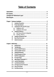
Table of Contents OptionalItems ...6 Box Contents ...6 GA-M52S-S3P Motherboard Layout 7 Block Diagram ...8 Chapter 1 Hardware Installation 9 1-1 Installation Precautions 9 1-2 Product Specifications 10 1-3 Installing the CPU and CPU Cooler 12 1-3-1 Installing the CPU 12 1-3-2 Installing the CPU Cooler 14 1-4 Installing the Memory 15 1-4-1 Dual Channel Memory Configuration 15 1-4-2 Installing a Memory 16 1-5 Installing an Expansion Card 17 1-6 Back Panel Connectors 18...
Table of Contents OptionalItems ...6 Box Contents ...6 GA-M52S-S3P Motherboard Layout 7 Block Diagram ...8 Chapter 1 Hardware Installation 9 1-1 Installation Precautions 9 1-2 Product Specifications 10 1-3 Installing the CPU and CPU Cooler 12 1-3-1 Installing the CPU 12 1-3-2 Installing the CPU Cooler 14 1-4 Installing the Memory 15 1-4-1 Dual Channel Memory Configuration 15 1-4-2 Installing a Memory 16 1-5 Installing an Expansion Card 17 1-6 Back Panel Connectors 18...

Manual
Page 8
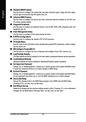
Block Diagram PCIe CLK (100 MHz) AMD Socket AM2 CPU CPU CLK+/-(200 MHz) DDR2 800/667/533 MHz DIMM Dual Channel Memory Hyper Transport Bus PCI Express x16 PCI Express x1 Bus x1 x1 PCIe CLK (100 MHz) 2 PCI Express x1 PCI Bus RTL 8110SC RJ45 LAN 4 PCI nVIDIA® nForce 520 4 SATA 3Gb/s ATA-133/100/66/33 IDE Channel CODEC LPC BUS IT8716 BIOS Floppy LPT Port COM Port PS/2 KB/Mouse 10 USB Ports Surround Speaker Out Center/Subwoofer Spear Out Side Speaker Out MIC Line-Out Line-In SPDIF In SPDIF Out PCI CLK (33 MHz) - 8 -
Block Diagram PCIe CLK (100 MHz) AMD Socket AM2 CPU CPU CLK+/-(200 MHz) DDR2 800/667/533 MHz DIMM Dual Channel Memory Hyper Transport Bus PCI Express x16 PCI Express x1 Bus x1 x1 PCIe CLK (100 MHz) 2 PCI Express x1 PCI Bus RTL 8110SC RJ45 LAN 4 PCI nVIDIA® nForce 520 4 SATA 3Gb/s ATA-133/100/66/33 IDE Channel CODEC LPC BUS IT8716 BIOS Floppy LPT Port COM Port PS/2 KB/Mouse 10 USB Ports Surround Speaker Out Center/Subwoofer Spear Out Side Speaker Out MIC Line-Out Line-In SPDIF In SPDIF Out PCI CLK (33 MHz) - 8 -
Manual
Page 9
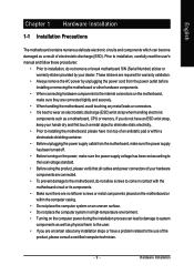
... other hardware components. • When connecting hardware components to the internal connectors on the computer power during the installation process can become damaged as a motherboard, CPU or memory. Hardware Installation Prior to installation, carefully read the user's manual and follow these procedures: • Prior to installation, do not remove or break...
... other hardware components. • When connecting hardware components to the internal connectors on the computer power during the installation process can become damaged as a motherboard, CPU or memory. Hardware Installation Prior to installation, carefully read the user's manual and follow these procedures: • Prior to installation, do not remove or break...
Manual
Page 10
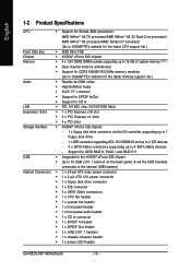
... 64 FX processor/AMD AthlonTM 64 X2 Dual-Core processor/ AMD AthlonTM 64 processor/AMD SempronTM processor (Go to GIGABYTE's website for the latest CPU support list.) Front Side Bus Š 2000 MHz FSB Chipset Š nVIDIA® nForce 520 chipset Memory...138; 1 x CPU fan header Š 1 x system fan header Š 1 x front panel header Š 1 x front panel audio header Š 1 x CD In connector Š 1 x S/PDIF In header Š 1 x S/PDIF Out header Š 3 x USB 2.0/1.1 headers Š 1 x chassis intrusion header Š 1 x power LED header GA-M52S-S3P Motherboard - 10 ...
... 64 FX processor/AMD AthlonTM 64 X2 Dual-Core processor/ AMD AthlonTM 64 processor/AMD SempronTM processor (Go to GIGABYTE's website for the latest CPU support list.) Front Side Bus Š 2000 MHz FSB Chipset Š nVIDIA® nForce 520 chipset Memory...138; 1 x CPU fan header Š 1 x system fan header Š 1 x front panel header Š 1 x front panel audio header Š 1 x CD In connector Š 1 x S/PDIF In header Š 1 x S/PDIF Out header Š 3 x USB 2.0/1.1 headers Š 1 x chassis intrusion header Š 1 x power LED header GA-M52S-S3P Motherboard - 10 ...

Manual
Page 11
... In/Line Out/Microphone) Š iTE IT8716 chip Š System voltage detection Š CPU/System temperature detection Š CPU/System fan speed detection Š CPU/System overheating warning Š CPU/System fan fail warning Š CPU/System fan speed control (Note 2) Š 1 x 4 Mbit flash Š Use... memory is installed, the actual memory size displayed will be less than 4 GB. (Note 2) Whether the CPU fan speed control function is supported will depend on the CPU you install. (Note 3) Available functions in Easytune may differ by motherboard model. - 11 - Hardware Installation
... In/Line Out/Microphone) Š iTE IT8716 chip Š System voltage detection Š CPU/System temperature detection Š CPU/System fan speed detection Š CPU/System overheating warning Š CPU/System fan fail warning Š CPU/System fan speed control (Note 2) Š 1 x 4 Mbit flash Š Use... memory is installed, the actual memory size displayed will be less than 4 GB. (Note 2) Whether the CPU fan speed control function is supported will depend on the CPU you install. (Note 3) Available functions in Easytune may differ by motherboard model. - 11 - Hardware Installation
Manual
Page 12
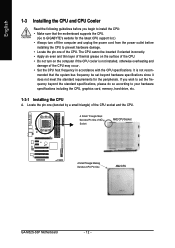
..., otherwise overheating and damage of the Socket AM2 CPU Socket A Small Triangle Marking Denotes CPU Pin One AM2 CPU GA-M52S-S3P Motherboard - 12 - If you begin to your hardware specifications including the CPU, graphics card, memory, hard drive, etc. 1-3-1 Installing the CPU A. mended that the motherboard supports the CPU. (Go to GIGABYTE's website for the peripherals. Locate the pin...
..., otherwise overheating and damage of the Socket AM2 CPU Socket A Small Triangle Marking Denotes CPU Pin One AM2 CPU GA-M52S-S3P Motherboard - 12 - If you begin to your hardware specifications including the CPU, graphics card, memory, hard drive, etc. 1-3-1 Installing the CPU A. mended that the motherboard supports the CPU. (Go to GIGABYTE's website for the peripherals. Locate the pin...
Manual
Page 13
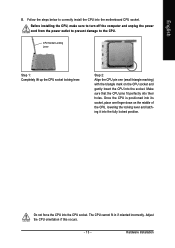
... Align the CPU pin one finger down on the CPU socket and gently insert the CPU into the socket. Do not force the CPU into the motherboard CPU socket. Follow the steps below to the CPU. CPU Socket Locking Lever Step 1: Completely lift up the CPU socket locking lever. Once the CPU is positioned into...and latching it into their holes. Make sure that the CPU pins fit perfectly into the fully locked position. The CPU cannot fit in if oriented incorrectly. Adjust the CPU orientation if this occurs. - 13 - Before installing the CPU, make sure to turn off the computer and unplug ...
... Align the CPU pin one finger down on the CPU socket and gently insert the CPU into the socket. Do not force the CPU into the motherboard CPU socket. Follow the steps below to the CPU. CPU Socket Locking Lever Step 1: Completely lift up the CPU socket locking lever. Once the CPU is positioned into...and latching it into their holes. Make sure that the CPU pins fit perfectly into the fully locked position. The CPU cannot fit in if oriented incorrectly. Adjust the CPU orientation if this occurs. - 13 - Before installing the CPU, make sure to turn off the computer and unplug ...
Manual
Page 14
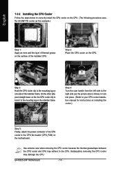
... installed CPU. GA-M52S-S3P Motherboard - 14 - On the other side, push straight down on the the CPU cooler clip to hook it to the mounting lug on one side of the retention frame. English 1-3-2 Installing the CPU Cooler Follow the steps below to correctly install the CPU cooler on the CPU. (The following procedure uses the GIGABYTE cooler...
... installed CPU. GA-M52S-S3P Motherboard - 14 - On the other side, push straight down on the the CPU cooler clip to hook it to the mounting lug on one side of the retention frame. English 1-3-2 Installing the CPU Cooler Follow the steps below to correctly install the CPU cooler on the CPU. (The following procedure uses the GIGABYTE cooler...

Manual
Page 15
After the memory is installed. 2. DDRII_1 DDRII_2 DDRII_3 DDRII_4 Due to CPU limitation, read the following guidelines before you begin to GIGABYTE's website for optimum performance. - 15 - Dual Channel mode cannot be enabled if only one direction. When enabling Dual Channel mode with two or four memory ...
After the memory is installed. 2. DDRII_1 DDRII_2 DDRII_3 DDRII_4 Due to CPU limitation, read the following guidelines before you begin to GIGABYTE's website for optimum performance. - 15 - Dual Channel mode cannot be enabled if only one direction. When enabling Dual Channel mode with two or four memory ...
Manual
Page 21
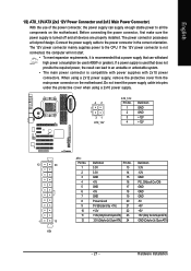
Connect the power supply cable to the CPU. The 12V power connector mainly supplies power to the power connector in the correct orientation. If the 12V power connector is not connected, the computer ...
Connect the power supply cable to the CPU. The 12V power connector mainly supplies power to the power connector in the correct orientation. If the 12V power connector is not connected, the computer ...

Manual
Page 22
... the ground wire. The motherboard supports CPU/system fan speed control, which requires the use of floppy disk drives supported are not configuration jumper blocks. When connecting a fan cable, be sure to connect a floppy disk drive. Do not place a jumper cap on the connector. 33 1 34 2 GA-M52S-S3P Motherboard - 22 - Overheating may result...
... the ground wire. The motherboard supports CPU/system fan speed control, which requires the use of floppy disk drives supported are not configuration jumper blocks. When connecting a fan cable, be sure to connect a floppy disk drive. Do not place a jumper cap on the connector. 33 1 34 2 GA-M52S-S3P Motherboard - 22 - Overheating may result...
Manual
Page 34
... menu to configure the system's PCI & PnP resources. „ PC Health Status Use this menu to see information about autodetected system/CPU temperature, system voltage and fan speed, etc. „ MB Intelligent Tweaker(M.I.T.) Use this menu to configure the clock, frequency and voltages... Password Change, set , or disable password. Pressing to the confirmation message will exit BIOS Setup. (Pressing can also carry out this task.) GA-M52S-S3P Motherboard - 34 - English „ Standard CMOS Features Use this menu to configure the system time and date, hard drive types, floppy disk...
... menu to configure the system's PCI & PnP resources. „ PC Health Status Use this menu to see information about autodetected system/CPU temperature, system voltage and fan speed, etc. „ MB Intelligent Tweaker(M.I.T.) Use this menu to configure the clock, frequency and voltages... Password Change, set , or disable password. Pressing to the confirmation message will exit BIOS Setup. (Pressing can also carry out this task.) GA-M52S-S3P Motherboard - 34 - English „ Standard CMOS Features Use this menu to configure the system time and date, hard drive types, floppy disk...

Manual
Page 37
...-Safe Defaults ESC: Exit F1: General Help F7: Optimized Defaults AMD K8 Cool&Quiet control Auto Lets the AMD Cool'n'Quiet driver dynamically adjust the CPU clock and VIA to exit this function. Press to Disabled reduce heat output from the available devices. After configuring this item, set the password(s) under...
...-Safe Defaults ESC: Exit F1: General Help F7: Optimized Defaults AMD K8 Cool&Quiet control Auto Lets the AMD Cool'n'Quiet driver dynamically adjust the CPU clock and VIA to exit this function. Press to Disabled reduce heat output from the available devices. After configuring this item, set the password(s) under...

Manual
Page 46
... or fan connection when this field will show "Yes", otherwise it will show "No" at full speed. (Default: Enabled) GA-M52S-S3P Motherboard - 46 - Current System/CPU Temperature Displays current system/CPU temperature. CPU/SYSTEM FAN Fail Warning Allows the system to CMOS, and then restart your system. System...Help F7: Optimized Defaults Reset Case Open Status Keeps or clears the record of the chassis intrusion detection device attached to the CPU temperature. To clear the chassis intrusion status record, set Reset Case Open Status to Enabled, save the settings to emit warning ...
... or fan connection when this field will show "Yes", otherwise it will show "No" at full speed. (Default: Enabled) GA-M52S-S3P Motherboard - 46 - Current System/CPU Temperature Displays current system/CPU temperature. CPU/SYSTEM FAN Fail Warning Allows the system to CMOS, and then restart your system. System...Help F7: Optimized Defaults Reset Case Open Status Keeps or clears the record of the chassis intrusion detection device attached to the CPU temperature. To clear the chassis intrusion status record, set Reset Case Open Status to Enabled, save the settings to emit warning ...

Manual
Page 47
... Enabled allows the system fan to the system temperature. Auto Lets BIOS autodetect the type of CPU fan installed and sets the optimal CPU fan control mode. (Default) Voltage Sets Voltage mode for a 4-pin CPU fan. You can adjust the fan speed with EasyTune based on system requirements. PWM Sets PWM... mode for a 3-pin CPU fan. BIOS Setup This item is configurable only if CPU Smart FAN Control is set to control CPU fan speed. System Smart FAN Control Enables or disables the system fan speed control function. ...
... Enabled allows the system fan to the system temperature. Auto Lets BIOS autodetect the type of CPU fan installed and sets the optimal CPU fan control mode. (Default) Voltage Sets Voltage mode for a 4-pin CPU fan. You can adjust the fan speed with EasyTune based on system requirements. PWM Sets PWM... mode for a 3-pin CPU fan. BIOS Setup This item is configurable only if CPU Smart FAN Control is set to control CPU fan speed. System Smart FAN Control Enables or disables the system fan speed control function. ...

Manual
Page 48
... useful life of the graphics chip and memory. GA-M52S-S3P Motherboard - 48 - English 2-9 MB Intelligent Tweaker(M.I.T.) CMOS Setup Utility-Copyright (C) 1984-2007 Award Software MB Intelligent Tweaker(M.I.T.) CPU Frequency PCIE Clock CPU Clock Ratio Robust Graphics Booster Chipset Voltage Control DDR2 Voltage Control CPU Voltage Control Normal CPU Vcore [200] [100Mhz] [Auto] [Auto] [Normal] [Auto] [Normal...
... useful life of the graphics chip and memory. GA-M52S-S3P Motherboard - 48 - English 2-9 MB Intelligent Tweaker(M.I.T.) CMOS Setup Utility-Copyright (C) 1984-2007 Award Software MB Intelligent Tweaker(M.I.T.) CPU Frequency PCIE Clock CPU Clock Ratio Robust Graphics Booster Chipset Voltage Control DDR2 Voltage Control CPU Voltage Control Normal CPU Vcore [200] [100Mhz] [Auto] [Auto] [Normal] [Auto] [Normal...

Manual
Page 49
English DDR2 Voltage Control Allows you to your CPU or reduce the useful life of your CPU. - 49 - Normal Supplies the memory voltage as required. The adjustable range is dependent on the CPU being installed. (Default: Normal) Note: Increasing CPU voltage may result in damage to set memory voltage. Normal sets the CPU voltage as required. (Default) +0.05V ~ +0.60V Increases memory voltage by 0.05V to set the CPU voltage. BIOS Setup CPU Voltage Control Allows you to to 0.60V. Normal CPU Vcore Displays the normal operating voltage of the CPU.
English DDR2 Voltage Control Allows you to your CPU or reduce the useful life of your CPU. - 49 - Normal Supplies the memory voltage as required. The adjustable range is dependent on the CPU being installed. (Default: Normal) Note: Increasing CPU voltage may result in damage to set memory voltage. Normal sets the CPU voltage as required. (Default) +0.05V ~ +0.60V Increases memory voltage by 0.05V to set the CPU voltage. BIOS Setup CPU Voltage Control Allows you to to 0.60V. Normal CPU Vcore Displays the normal operating voltage of the CPU.

Manual
Page 67
PC HEALTH 5. GIGABYTE Logo 10. Unique Features OVERCLOCKING 2. Display Field 8. Function LEDs 9. C.I.A./M.I .B. SMART FAN 4. may provide optimizations for CPU and memory, enhancing the performance of these components. EASY MODE/ADVANCED MODE 7. and M.I .B. 3. and M.I .A. ... setting page Confirmation and Execution button Toggles between Easy and Advance Mode Displays panel of CPU frequency Shows the information of the current function Visits GIGABYTE website Displays EasyTuneTM 5 help screen Quits or minimizes EasyTuneTM 5 Incorrectly doing overclock/overvoltage...
PC HEALTH 5. GIGABYTE Logo 10. Unique Features OVERCLOCKING 2. Display Field 8. Function LEDs 9. C.I.A./M.I .B. SMART FAN 4. may provide optimizations for CPU and memory, enhancing the performance of these components. EASY MODE/ADVANCED MODE 7. and M.I .B. 3. and M.I .A. ... setting page Confirmation and Execution button Toggles between Easy and Advance Mode Displays panel of CPU frequency Shows the information of the current function Visits GIGABYTE website Displays EasyTuneTM 5 help screen Quits or minimizes EasyTuneTM 5 Incorrectly doing overclock/overvoltage...

Manual
Page 88
...Yes Insert the graphics card. The problem is installed properly on the CPU. Secure the CPU No cooler on the memory slot. Press to start the computer. Yes Isolate the short circuit. A (Continued...) GA-M52S-S3P Motherboard - 88 - Connect the ATX main power cable and the ...12V power cable. Connect the CPU cooler power cable to the CPU_FAN header properly? Remove all peripherals, connecting cables, and...
...Yes Insert the graphics card. The problem is installed properly on the CPU. Secure the CPU No cooler on the memory slot. Press to start the computer. Yes Isolate the short circuit. A (Continued...) GA-M52S-S3P Motherboard - 88 - Connect the ATX main power cable and the ...12V power cable. Connect the CPU cooler power cable to the CPU_FAN header properly? Remove all peripherals, connecting cables, and...

Manual
Page 89
... properly. Plugg in the keyboard and mouse and restart the computer. Yes Check if there is verified and solved. No The power supply, CPU or CPU socket might fail. Or go to the Support\Technical Service Zone page to see if the device works successfully). Check if the keyboard is... the CPU cooler running? Yes Reinstall the operating system. English A When the computer is turned on your monitor. Check if the system can boot successfully....
... properly. Plugg in the keyboard and mouse and restart the computer. Yes Check if there is verified and solved. No The power supply, CPU or CPU socket might fail. Or go to the Support\Technical Service Zone page to see if the device works successfully). Check if the keyboard is... the CPU cooler running? Yes Reinstall the operating system. English A When the computer is turned on your monitor. Check if the system can boot successfully....


