User Manual
Page 4
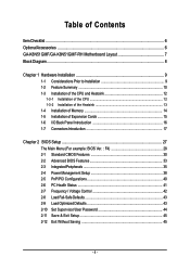
Table of Contents ItemChecklist ...6 OptionalAccessories ...6 GA-K8N51GMF/GA-K8N51GMF-RH Motherboard Layout 7 Block Diagram ...8 Chapter 1 Hardware Installation 9 1-1 Considerations Prior to Installation 9 1-2 Feature Summary 10 1-3 Installation of the CPU and Heatsink 12 1-3-1 Installation of the CPU 12 1-3-2 Installation of the Heatsink 13 1-4 Installation of Memory 14 1-5 Installation of Expansion Cards 15 1-6 I/O Back Panel Introduction 16 1-7 Connectors Introduction 17...
Table of Contents ItemChecklist ...6 OptionalAccessories ...6 GA-K8N51GMF/GA-K8N51GMF-RH Motherboard Layout 7 Block Diagram ...8 Chapter 1 Hardware Installation 9 1-1 Considerations Prior to Installation 9 1-2 Feature Summary 10 1-3 Installation of the CPU and Heatsink 12 1-3-1 Installation of the CPU 12 1-3-2 Installation of the Heatsink 13 1-4 Installation of Memory 14 1-5 Installation of Expansion Cards 15 1-6 I/O Back Panel Introduction 16 1-7 Connectors Introduction 17...
User Manual
Page 9
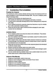
...or any hardware, please first carefully read the information in the provided manual. 3. Please do not allow screws to be an unofficial Gigabyte product. - 9 - Instances of violating the conditions recommended in contact with the motherboard circuit or its power cord. 2. Damage ... the motherboard or within a electrostatic shielding container. 5. Damage due to wear an electrostatic discharge (ESD) cuff when handling electronic components (CPU, RAM). 4. These stickers are no leftover screws or metal components placed on an uneven surface. 7. Please make sure there are required...
...or any hardware, please first carefully read the information in the provided manual. 3. Please do not allow screws to be an unofficial Gigabyte product. - 9 - Instances of violating the conditions recommended in contact with the motherboard circuit or its power cord. 2. Damage ... the motherboard or within a electrostatic shielding container. 5. Damage due to wear an electrostatic discharge (ESD) cuff when handling electronic components (CPU, RAM). 4. These stickers are no leftover screws or metal components placed on an uneven surface. 7. Please make sure there are required...

User Manual
Page 10
...Speaker Out ; Line Out (Front Speaker Out) ; Surround Speaker Out (Rear Speaker Out) ; English 1-2 Feature Summary CPU Š Socket 754 for additional 1 port by cables Š 1 IEEE1394 connector for AMD AthlonTM 64 processor (K8...2 SATA 3Gb/s connectors Š 1 CPU fan connector Š 1 system fan connector Š 1 front panel connector Š 1 front audio connector Š 1 CD In connector Š 2 USB 2.0/1.1 connectors for additional 4 USB 2.0/1.1 ports by cable Š 1 SPDIF In/Out connector Š 1 power LED connector GA-K8N51GMF(-RH) Motherboard - 10 -
...Speaker Out ; Line Out (Front Speaker Out) ; Surround Speaker Out (Rear Speaker Out) ; English 1-2 Feature Summary CPU Š Socket 754 for additional 1 port by cables Š 1 IEEE1394 connector for AMD AthlonTM 64 processor (K8...2 SATA 3Gb/s connectors Š 1 CPU fan connector Š 1 system fan connector Š 1 front panel connector Š 1 front audio connector Š 1 CD In connector Š 2 USB 2.0/1.1 connectors for additional 4 USB 2.0/1.1 ports by cable Š 1 SPDIF In/Out connector Š 1 power LED connector GA-K8N51GMF(-RH) Motherboard - 10 -

User Manual
Page 11
...Speaker Out) I/O Control Š Winbond W83627 chip Hardware Monitor Š System voltage detection Š CPU / System temperature detection Š CPU / System fan speed detection Š CPU warning temperature Š Supports CPU Smart Fan function(Note 1) BIOS Š 1 4Mbit flash ROM Š Use of licensed AWARD ...Internet Security (OEM version) Form Factor Š Micro ATX form factor; 24.4cm x 22.0cm (Note 1) Whether the CPU Smart FAN Control function is supported will depend on different motherboards. - 11 - For more detailed information please check at the FAQ section ...
...Speaker Out) I/O Control Š Winbond W83627 chip Hardware Monitor Š System voltage detection Š CPU / System temperature detection Š CPU / System fan speed detection Š CPU warning temperature Š Supports CPU Smart Fan function(Note 1) BIOS Š 1 4Mbit flash ROM Š Use of licensed AWARD ...Internet Security (OEM version) Form Factor Š Micro ATX form factor; 24.4cm x 22.0cm (Note 1) Whether the CPU Smart FAN Control function is supported will depend on different motherboards. - 11 - For more detailed information please check at the FAQ section ...
User Manual
Page 12
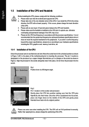
... 2. The pin 1 location is positioned into place. Move the socket lever to system use extra care when installing the CPU. Align the processor to see that the CPU pins fitperfectly into the socket. GA-K8N51GMF(-RH) Motherboard - 12 - If you wish to set beyond the proper specifications, please do so according to your hardware...
... 2. The pin 1 location is positioned into place. Move the socket lever to system use extra care when installing the CPU. Align the processor to see that the CPU pins fitperfectly into the socket. GA-K8N51GMF(-RH) Motherboard - 12 - If you wish to set beyond the proper specifications, please do so according to your hardware...
User Manual
Page 13
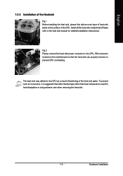
... sink manual for heat dissipation or using extreme care when removing the heat sink. - 13 - Install all the heat sink components (Please refer to the CPU as a result of hardening of the CPU. To prevent such an occurrence, it is suggested that the heat sink can properly function to prevent...
... sink manual for heat dissipation or using extreme care when removing the heat sink. - 13 - Install all the heat sink components (Please refer to the CPU as a result of hardening of the CPU. To prevent such an occurrence, it is suggested that the heat sink can properly function to prevent...

User Manual
Page 18
...power supply is used (300W or greater). Otherwise, please do not remove it. 42 31 Pin No. 1 2 3 4 Definition GND GND +12V +12V GA-K8N51GMF(-RH) Motherboard Pin No. The ATX_12V power connector mainly supplies power to an unstable system or a system that is not connected, the system will not...24 GND - 18 - English 1/2) ATX_12V / ATX (Power Connector) With the use of the power connector, the power supply can lead to the CPU. Please use a power supply that is recommended that a power supply that can withstand high power consumption be used that all the components on the ...
...power supply is used (300W or greater). Otherwise, please do not remove it. 42 31 Pin No. 1 2 3 4 Definition GND GND +12V +12V GA-K8N51GMF(-RH) Motherboard Pin No. The ATX_12V power connector mainly supplies power to an unstable system or a system that is not connected, the system will not...24 GND - 18 - English 1/2) ATX_12V / ATX (Power Connector) With the use of the power connector, the power supply can lead to the CPU. Please use a power supply that is recommended that a power supply that can withstand high power consumption be used that all the components on the ...

User Manual
Page 19
... cable while the other end of FDD drives supported are designed with color-coded power connector wires. The types of the cable connects to prevent CPU overheating and failure. 1 CPU_FAN 1 SYS_FAN Pin No. 1 2 3 Definition GND +12V Sense 5) FDD (FDD Connector) The FDD connector is the ground wire (GND). Hardware Installation.... Please remember to connect the power to the cooler to the pin1 position. 34 33 2 1 - 19 - Please remember to connect the power to the CPU fan to the FDD drive. A red power connector wire indicates a positive connection and requires a +12V power voltage.
... cable while the other end of FDD drives supported are designed with color-coded power connector wires. The types of the cable connects to prevent CPU overheating and failure. 1 CPU_FAN 1 SYS_FAN Pin No. 1 2 3 Definition GND +12V Sense 5) FDD (FDD Connector) The FDD connector is the ground wire (GND). Hardware Installation.... Please remember to connect the power to the cooler to the pin1 position. 34 33 2 1 - 19 - Please remember to connect the power to the CPU fan to the FDD drive. A red power connector wire indicates a positive connection and requires a +12V power voltage.

User Manual
Page 29
It allows you to limit access to the system and Setup, or just to control CPU clock and frequency ratio. „ Load Fail-Safe Defaults Fail-Safe Defaults indicates the value of the system parameters which the system would be in ...
It allows you to limit access to the system and Setup, or just to control CPU clock and frequency ratio. „ Load Fail-Safe Defaults Fail-Safe Defaults indicates the value of the system parameters which the system would be in ...
User Manual
Page 32
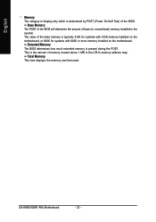
Extended Memory The BIOS determines how much extended memory is present during the POST. GA-K8N51GMF(-RH) Motherboard - 32 - This is the amount of base (or conventional) memory installed in the CPU's memory address map. Base Memory The POST of the BIOS will determine the amount of memory located above 1 MB in the system...
Extended Memory The BIOS determines how much extended memory is present during the POST. GA-K8N51GMF(-RH) Motherboard - 32 - This is the amount of base (or conventional) memory installed in the CPU's memory address map. Base Memory The POST of the BIOS will determine the amount of memory located above 1 MB in the system...

User Manual
Page 41
... your computer will run at next boot. If you install. CPU Smart FAN Control (Note) Disabled Disable this function. (Default value) Enabled When this function is closed, Case Opened will depend on GIGABYTE's website. - 41 - BIOS Setup Users can adjust the fan... speed with Easy Tune based on CPU temperature. Case Opened If the case is enabled, CPU fan will restart. System/CPU Temperature Detect system/CPU temperature automatically. Current Voltage(V) VCORE / DDR...
... your computer will run at next boot. If you install. CPU Smart FAN Control (Note) Disabled Disable this function. (Default value) Enabled When this function is closed, Case Opened will depend on GIGABYTE's website. - 41 - BIOS Setup Users can adjust the fan... speed with Easy Tune based on CPU temperature. Case Opened If the case is enabled, CPU fan will restart. System/CPU Temperature Detect system/CPU temperature automatically. Current Voltage(V) VCORE / DDR...
User Manual
Page 42
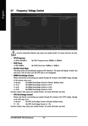
...using it may cause your system broken. Incorrect using it may cause your system broken. GA-K8N51GMF(-RH) Motherboard - 42 - DIMM OverVoltage Control Please note that by CPU detection. Normal Set DIMM OverVoltage Control to Normal. (Default value) +0.1V Set DIMM ... English 2-7 Frequency / Voltage Control CMOS Setup Utility-Copyright (C) 1984-2005 Award Software Frequency / Voltage Control CPU Frequency PCIE Clock K8 CPU Clock Ratio DIMM OverVoltage Control CPU OverVoltage Control Robust Graphics Booster [200.0] [100Mhz] [Default] [Normal] [Normal] [Auto] Item Help...
...using it may cause your system broken. Incorrect using it may cause your system broken. GA-K8N51GMF(-RH) Motherboard - 42 - DIMM OverVoltage Control Please note that by CPU detection. Normal Set DIMM OverVoltage Control to Normal. (Default value) +0.1V Set DIMM ... English 2-7 Frequency / Voltage Control CMOS Setup Utility-Copyright (C) 1984-2005 Award Software Frequency / Voltage Control CPU Frequency PCIE Clock K8 CPU Clock Ratio DIMM OverVoltage Control CPU OverVoltage Control Robust Graphics Booster [200.0] [100Mhz] [Default] [Normal] [Normal] [Auto] Item Help...

User Manual
Page 51
...2) is a revolutionary eight-phase power circuit built for download. With GIGABYTE's proprietary S.O.S. These characteristics make it the ideal companion with the option for ultimate system protection. C.I.A.2 (CPU Intelligent Accelerator 2) GIGABYTE CPU Intelligent Accelerator 2(C.I .T.'s integration of all platform performance settings into different ...modes within BIOS setup in order to change system settings such as the CPU system bus, memory timings or to enabled Gigabyte's unique C.I.A. 2 and M.I .T.) allows user to provide a more user-friendly and ...
...2) is a revolutionary eight-phase power circuit built for download. With GIGABYTE's proprietary S.O.S. These characteristics make it the ideal companion with the option for ultimate system protection. C.I.A.2 (CPU Intelligent Accelerator 2) GIGABYTE CPU Intelligent Accelerator 2(C.I .T.'s integration of all platform performance settings into different ...modes within BIOS setup in order to change system settings such as the CPU system bus, memory timings or to enabled Gigabyte's unique C.I.A. 2 and M.I .T.) allows user to provide a more user-friendly and ...

User Manual
Page 52
... for enhancing system performance, 2) C.I .B. Function display LEDs 9. GA-K8N51GMF(-RH) Motherboard - 52 - for special enhancement for CPU and Memory, 3) Smart-Fan control for managing fan speed control of CPU frequency Shows the current functions status Log on different motherboards. PC Health 5. "Easy Mode" & "Advance Mode" 7. Display screen 8. GIGABYTE Logo 10. GO 6. Smart-Fan 4. Exit or...
... for enhancing system performance, 2) C.I .B. Function display LEDs 9. GA-K8N51GMF(-RH) Motherboard - 52 - for special enhancement for CPU and Memory, 3) Smart-Fan control for managing fan speed control of CPU frequency Shows the current functions status Log on different motherboards. PC Health 5. "Easy Mode" & "Advance Mode" 7. Display screen 8. GIGABYTE Logo 10. GO 6. Smart-Fan 4. Exit or...


