
Manual
Page 4
Table of Contents Box Contents ...6 OptionalItems ...6 GA-EP45-UD3R/UD3 Motherboard Layout 7 Block Diagram ...8 Chapter 1 Hardware Installation 9 1-1 Installation Precautions 9 1-2 Product Specifications 10 1-3 Installing the CPU and CPU Cooler 13 1-3-1 Installing the CPU 13 1-3-2 Installing the CPU Cooler 15 1-4 Installing the Memory 16 1-4-1 Dual Channel Memory Configuration 16 1-4-2 Installing a Memory 17 1-5 Installing an Expansion Card 18 1-6 Installing the SATA Bracket 19 1-7 Back Panel Connectors...
Table of Contents Box Contents ...6 OptionalItems ...6 GA-EP45-UD3R/UD3 Motherboard Layout 7 Block Diagram ...8 Chapter 1 Hardware Installation 9 1-1 Installation Precautions 9 1-2 Product Specifications 10 1-3 Installing the CPU and CPU Cooler 13 1-3-1 Installing the CPU 13 1-3-2 Installing the CPU Cooler 15 1-4 Installing the Memory 16 1-4-1 Dual Channel Memory Configuration 16 1-4-2 Installing a Memory 17 1-5 Installing an Expansion Card 18 1-6 Installing the SATA Bracket 19 1-7 Back Panel Connectors...
Manual
Page 5
... Controllers1 83 5-1-2 Configuring GIGABYTE SATA2 SATA Controller 89 5-1-3 Making a SATA RAID/AHCI Driver Diskette 95 5-1-4 Installing the SATA RAID/AHCI ...Driver and Operating System 97 5-2 ConfiguringAudio Input and Output 105 5-2-1 Configuring 2/4/5.1/7.1-Channel Audio 105 5-2-2 Installing the S/PDIF In Cable (Optional 107 5-2-3 Configuring Microphone Recording 108 5-2-4 Using the Sound Recorder 110 5-3 Troubleshooting 111 5-3-1 Frequently Asked Questions 111 5-3-2 Troubleshooting Procedure 112 5-4 Regulatory Statements 114 1 Only for GA-EP45-UD3R...
... Controllers1 83 5-1-2 Configuring GIGABYTE SATA2 SATA Controller 89 5-1-3 Making a SATA RAID/AHCI Driver Diskette 95 5-1-4 Installing the SATA RAID/AHCI ...Driver and Operating System 97 5-2 ConfiguringAudio Input and Output 105 5-2-1 Configuring 2/4/5.1/7.1-Channel Audio 105 5-2-2 Installing the S/PDIF In Cable (Optional 107 5-2-3 Configuring Microphone Recording 108 5-2-4 Using the Sound Recorder 110 5-3 Troubleshooting 111 5-3-1 Frequently Asked Questions 111 5-3-2 Troubleshooting Procedure 112 5-4 Regulatory Statements 114 1 Only for GA-EP45-UD3R...

Manual
Page 6
The box contents are for reference only. Box Contents GA-EP45-UD3R or GA-EP45-UD3 motherboard Motherboard driver disk User's Manual Quick Installation Guide One IDE cable Four SATA 3Gb/s cables One SATA bracket I/O Shield Only for GA-EP45-UD3R. • The box contents above are subject to change without notice. • The motherboard image is for...
The box contents are for reference only. Box Contents GA-EP45-UD3R or GA-EP45-UD3 motherboard Motherboard driver disk User's Manual Quick Installation Guide One IDE cable Four SATA 3Gb/s cables One SATA bracket I/O Shield Only for GA-EP45-UD3R. • The box contents above are subject to change without notice. • The motherboard image is for...

Manual
Page 9
... and components which can lead to damage to the use of the product, please consult a certified computer technician. - 9 - Hardware Installation These stickers are required for warranty validation. • Always remove the AC power by your hardware components are connected. • To ...on the motherboard or within an electrostatic shielding container. • Before unplugging the power supply cable from the power outlet before installing or removing the motherboard or other hardware components. • When connecting hardware components to the internal connectors on the motherboard,...
... and components which can lead to damage to the use of the product, please consult a certified computer technician. - 9 - Hardware Installation These stickers are required for warranty validation. • Always remove the AC power by your hardware components are connected. • To ...on the motherboard or within an electrostatic shielding container. • Before unplugging the power supply cable from the power outlet before installing or removing the motherboard or other hardware components. • When connecting hardware components to the internal connectors on the motherboard,...
Manual
Page 11
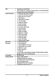
Hardware Installation USB Š Integrated in the South Bridge Š Up to 12 USB 2.0/1.1 ports (8 on the back panel, 4 via the USB brackets connected to the internal ...
Hardware Installation USB Š Integrated in the South Bridge Š Up to 12 USB 2.0/1.1 ports (8 on the back panel, 4 via the USB brackets connected to the internal ...

Manual
Page 12
GA-EP45-UD3R/UD3 Motherboard - 12 - BIOS Unique Features Bundled Software Operating System Form Factor Š 2 x... Š Support for Q-Flash Š Support for Virtual Dual BIOS Š Support for Download Center Š Support for Xpress Install Š Support for Xpress Recovery2 Š Support for EasyTune (Note 3) Š Support for Dynamic Energy Saver Advanced Š ... 1) Due to Windows Vista/XP 32-bit operating system limitation, when more than 4 GB of physical memory is installed, the actual memory size displayed will be less than 4 GB. (Note 2) Whether the CPU/System fan speed ...
GA-EP45-UD3R/UD3 Motherboard - 12 - BIOS Unique Features Bundled Software Operating System Form Factor Š 2 x... Š Support for Q-Flash Š Support for Virtual Dual BIOS Š Support for Download Center Š Support for Xpress Install Š Support for Xpress Recovery2 Š Support for EasyTune (Note 3) Š Support for Dynamic Energy Saver Advanced Š ... 1) Due to Windows Vista/XP 32-bit operating system limitation, when more than 4 GB of physical memory is installed, the actual memory size displayed will be less than 4 GB. (Note 2) Whether the CPU/System fan speed ...

Manual
Page 13
...set beyond the standard specifications, please do so according to your hardware specifications including the CPU, graphics card, memory, hard drive, etc. 1-3-1 Installing the CPU A. Locate the alignment keys on the motherboard CPU socket and the notches on the CPU - 13 - If you may locate ... the CPU cooler is not recom- mended that the motherboard supports the CPU. (Go to GIGABYTE's website for the peripherals. 1-3 Installing the CPU and CPU Cooler Read the following guidelines before installing the CPU to prevent hardware damage. • Locate the pin one of the CPU Socket...
...set beyond the standard specifications, please do so according to your hardware specifications including the CPU, graphics card, memory, hard drive, etc. 1-3-1 Installing the CPU A. Locate the alignment keys on the motherboard CPU socket and the notches on the CPU - 13 - If you may locate ... the CPU cooler is not recom- mended that the motherboard supports the CPU. (Go to GIGABYTE's website for the peripherals. 1-3 Installing the CPU and CPU Cooler Read the following guidelines before installing the CPU to prevent hardware damage. • Locate the pin one of the CPU Socket...

Manual
Page 14
Step 5: Once the CPU is not installed.) Step 4: Hold the CPU with the socket alignment keys) and gently insert the CPU into the motherboard CPU socket. GA-EP45-UD3R/UD3 Motherboard - 14 - Step 2: Lift the metal load plate from the CPU socket. (DO NOT touch socket contacts.) Step 3: Remove the protective socket ...pin one corner of the CPU socket (or you may align the CPU notches with your thumb and index fingers. Before installing the CPU, make sure to correctly install the CPU into position. Follow the steps below to turn off the computer and unplug the power cord from the load ...
Step 5: Once the CPU is not installed.) Step 4: Hold the CPU with the socket alignment keys) and gently insert the CPU into the motherboard CPU socket. GA-EP45-UD3R/UD3 Motherboard - 14 - Step 2: Lift the metal load plate from the CPU socket. (DO NOT touch socket contacts.) Step 3: Remove the protective socket ...pin one corner of the CPU socket (or you may align the CPU notches with your thumb and index fingers. Before installing the CPU, make sure to correctly install the CPU into position. Follow the steps below to turn off the computer and unplug the power cord from the load ...

Manual
Page 15
... extreme care when removing the CPU cooler because the thermal grease/tape between the CPU cooler and CPU may damage the CPU. - 15 - 1-3-2 Installing the CPU Cooler Follow the steps below to the CPU. Step 4: You should hear a "click" when pushing down on the contrary, is complete...as the example cooler.) Step 1: Apply an even and thin layer of thermal grease on the motherboard. Hardware Installation Inadequately removing the CPU cooler may adhere to correctly install the CPU cooler on the motherboard. (The following procedure uses Intel® boxed cooler as the picture above,...
... extreme care when removing the CPU cooler because the thermal grease/tape between the CPU cooler and CPU may damage the CPU. - 15 - 1-3-2 Installing the CPU Cooler Follow the steps below to the CPU. Step 4: You should hear a "click" when pushing down on the contrary, is complete...as the example cooler.) Step 1: Apply an even and thin layer of thermal grease on the motherboard. Hardware Installation Inadequately removing the CPU cooler may adhere to correctly install the CPU cooler on the motherboard. (The following procedure uses Intel® boxed cooler as the picture above,...

Manual
Page 16
...by allowing different memory sizes to be enabled if only one direction. GA-EP45-UD3R/UD3 Motherboard - 16 - It is recommended that memory of the same capacity, brand, speed, and chips be used . (Go to GIGABYTE's website for optimum performance. Enabling Dual Channel memory mode will appear... DDR2 sockets for the latest memory support list.) • Always turn off the computer and unplug the power cord from the power outlet before installing the memory to prevent hardware damage. • Memory modules have a foolproof design. After the memory is operating in Dual Channel mode. 1. ...
...by allowing different memory sizes to be enabled if only one direction. GA-EP45-UD3R/UD3 Motherboard - 16 - It is recommended that memory of the same capacity, brand, speed, and chips be used . (Go to GIGABYTE's website for optimum performance. Enabling Dual Channel memory mode will appear... DDR2 sockets for the latest memory support list.) • Always turn off the computer and unplug the power cord from the power outlet before installing the memory to prevent hardware damage. • Memory modules have a foolproof design. After the memory is operating in Dual Channel mode. 1. ...

Manual
Page 17
... module , make sure to turn off the computer and unplug the power cord from the power outlet to prevent damage to install DDR2 DIMMs on this motherboard. Step 2: The clips at both ends of the memory, push down on the top edge of the socket will snap ... module is securely inserted. - 17 - Place the memory module on the left, place your memory modules in one direction. Follow the steps below to correctly install your fingers on the memory and insert it can only fit in the memory sockets. As indicated in the picture on the socket. Spread the...
... module , make sure to turn off the computer and unplug the power cord from the power outlet to prevent damage to install DDR2 DIMMs on this motherboard. Step 2: The clips at both ends of the memory, push down on the top edge of the socket will snap ... module is securely inserted. - 17 - Place the memory module on the left, place your memory modules in one direction. Follow the steps below to correctly install your fingers on the memory and insert it can only fit in the memory sockets. As indicated in the picture on the socket. Spread the...

Manual
Page 18
...card. Carefully read the manual that supports your computer. Align the card with a screw. 5. GA-EP45-UD3R/UD3 Motherboard - 18 - 1-5 Installing an Expansion Card Read the following guidelines before installing an expansion card to prevent hardware damage. Locate an expansion slot that came with the expansion ...not rock. • Removing the Graphics Card: Gently push back on the lever on your card. Example: Installing and Removing a PCI Express Graphics Card: • Installing a Graphics Card: Gently push down on the top edge of the card until it is securely seated in ...
...card. Carefully read the manual that supports your computer. Align the card with a screw. 5. GA-EP45-UD3R/UD3 Motherboard - 18 - 1-5 Installing an Expansion Card Read the following guidelines before installing an expansion card to prevent hardware damage. Locate an expansion slot that came with the expansion ...not rock. • Removing the Graphics Card: Gently push back on the lever on your card. Example: Installing and Removing a PCI Express Graphics Card: • Installing a Graphics Card: Gently push down on the top edge of the card until it is securely seated in ...

Manual
Page 19
...sure to hardware. • Insert the SATA signal cable and SATA power cable securely into to the chassis back panel with the GA-EP45-UD3R only. - 19 - 1-6 Installing the SATA Bracket The SATA bracket1 allows you only need to the SATA port on your motherboard. nector on the power supply before... SATA signal cable and SATA power cable to the power connector on Step 5: the bracket. the external SATA con- Hardware Installation Follow the steps below to install the SATA bracket: Step 1: Locate one SATA power cable. Connect the other ends of the cable from the bracket to ...
...sure to hardware. • Insert the SATA signal cable and SATA power cable securely into to the chassis back panel with the GA-EP45-UD3R only. - 19 - 1-6 Installing the SATA Bracket The SATA bracket1 allows you only need to the SATA port on your motherboard. nector on the power supply before... SATA signal cable and SATA power cable to the power connector on Step 5: the bracket. the external SATA con- Hardware Installation Follow the steps below to install the SATA bracket: Step 1: Locate one SATA power cable. Connect the other ends of the cable from the bracket to ...
Manual
Page 21
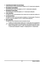
... a 4/5.1/7.1-channel audio configuration. In addition to the default speakers settings, the ~ audio jacks can be reconfigured to perform different functions via the audio software. Hardware Installation
... a 4/5.1/7.1-channel audio configuration. In addition to the default speakers settings, the ~ audio jacks can be reconfigured to perform different functions via the audio software. Hardware Installation

Manual
Page 22
...) CLR_CMOS 22) BAT 23) PHASE LED Read the following guidelines before turning on the motherboard. GA-EP45-UD3R/UD3 Motherboard - 22 - Unplug the power cord from the power outlet to prevent damage to the devices. • After installing the device and before connecting external devices: • First make sure the device cable has been... securely attached to the connector on the computer, make sure your devices are compliant with the connectors you wish to connect. • Before installing the devices, be sure to turn off the devices and your computer.
...) CLR_CMOS 22) BAT 23) PHASE LED Read the following guidelines before turning on the motherboard. GA-EP45-UD3R/UD3 Motherboard - 22 - Unplug the power cord from the power outlet to prevent damage to the devices. • After installing the device and before connecting external devices: • First make sure the device cable has been... securely attached to the connector on the computer, make sure your devices are compliant with the connectors you wish to connect. • Before installing the devices, be sure to turn off the devices and your computer.

Manual
Page 23
Hardware Installation Connect the power supply cable to the CPU. If the 12V power connector is not connected, the computer will not start. • Use of the ... supply that does not provide the required power, the result can withstand high power consumption be used that can lead to all devices are properly installed. Definition 1 GND (Only for 2x4 pin 12V) 2 GND (Only for 2x4 pin 12V) 3 GND 4 GND 5 +12V (Only for 2x4 pin 12V) 6 +12V (Only for 2x12...
Hardware Installation Connect the power supply cable to the CPU. If the 12V power connector is not connected, the computer will not start. • Use of the ... supply that does not provide the required power, the result can withstand high power consumption be used that can lead to all devices are properly installed. Definition 1 GND (Only for 2x4 pin 12V) 2 GND (Only for 2x4 pin 12V) 3 GND 4 GND 5 +12V (Only for 2x4 pin 12V) 6 +12V (Only for 2x12...

Manual
Page 24
... a 4-pin CPU fan header (CPU_FAN), a 3-pin (SYS_FAN1) and a 4-pin (SYS_FAN2) system fan headers, and a 3-pin power fan header (PWR_FAN). Before connecting a floppy disk drive, be installed inside the chassis. Overheating may result in the correct orientation (the black connector wire is recommended that a system fan be sure to locate pin 1 of..., and 2.88 MB. Most fan headers possess a foolproof insertion design. For purchasing the optional floppy disk drive cable, please contact the local dealer. 33 1 34 2 GA-EP45-UD3R/UD3 Motherboard - 24 -
... a 4-pin CPU fan header (CPU_FAN), a 3-pin (SYS_FAN1) and a 4-pin (SYS_FAN2) system fan headers, and a 3-pin power fan header (PWR_FAN). Before connecting a floppy disk drive, be installed inside the chassis. Overheating may result in the correct orientation (the black connector wire is recommended that a system fan be sure to locate pin 1 of..., and 2.88 MB. Most fan headers possess a foolproof insertion design. For purchasing the optional floppy disk drive cable, please contact the local dealer. 33 1 34 2 GA-EP45-UD3R/UD3 Motherboard - 24 -

Manual
Page 25
... ICH10R, Orange) The SATA connectors conform to two IDE devices such as hard drives and optical drives. Each SATA connector supports a single SATA device. Hardware Installation Before attaching the IDE cable, locate the foolproof groove on configuring a RAID array. If more than two hard drives are compatible with SATA 1.5Gb/s standard...
... ICH10R, Orange) The SATA connectors conform to two IDE devices such as hard drives and optical drives. Each SATA connector supports a single SATA device. Hardware Installation Before attaching the IDE cable, locate the foolproof groove on configuring a RAID array. If more than two hard drives are compatible with SATA 1.5Gb/s standard...

Manual
Page 27
... may issue beeps in S1 sleep state. Message/Power/ Power Sleep LED Switch Speaker MSG+ MSG- The system reports system startup status by chassis. Hardware Installation PW+ PWSPEAK+ SPEAK- 2 20 1 19 HD+ HD- The LED keeps blinking when S1 Blinking the system is detected at system startup. A front panel module mainly...
... may issue beeps in S1 sleep state. Message/Power/ Power Sleep LED Switch Speaker MSG+ MSG- The system reports system startup status by chassis. Hardware Installation PW+ PWSPEAK+ SPEAK- 2 20 1 19 HD+ HD- The LED keeps blinking when S1 Blinking the system is detected at system startup. A front panel module mainly...
Manual
Page 29
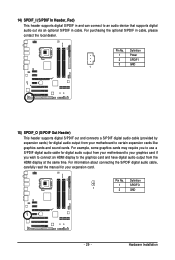
... the graphics card and have digital audio output from your graphics card if you to use a S/PDIF digital audio cable for your expansion card. Hardware Installation Pin No. Definition 1 SPDIFO 1 2 GND - 29 - Definition 1 Power 2 SPDIFI 3 GND 1 15) SPDIF_O (S/PDIF Out Header) This header supports digital S/PDIF out and connects a S/PDIF digital...
... the graphics card and have digital audio output from your graphics card if you to use a S/PDIF digital audio cable for your expansion card. Hardware Installation Pin No. Definition 1 SPDIFO 1 2 GND - 29 - Definition 1 Power 2 SPDIFI 3 GND 1 15) SPDIF_O (S/PDIF Out Header) This header supports digital S/PDIF out and connects a S/PDIF digital...


