

Manual
Page 1
GA-D525TUD Support Intel® Dual-core Atom™ D525 processor GA-D425TUD Support Intel® Single-core Atom™ D425 processor User's Manual Rev. 1302 12ME-525TUD-1302R
GA-D525TUD Support Intel® Dual-core Atom™ D525 processor GA-D425TUD Support Intel® Single-core Atom™ D425 processor User's Manual Rev. 1302 12ME-525TUD-1302R
Manual
Page 3
... information. Example: No part of this manual may be reproduced, copied, translated, transmitted, or published in this product, GIGABYTE provides the following types of GIGABYTE. For example, "REV: 1.0" means the revision of the motherboard is the property of documentations: For detailed ... For instructions on how to the specifications and features in this manual may be made by any form or by GIGABYTE without GIGABYTE's prior written permission. Copyright © 2010 GIGA-BYTE TECHNOLOGY CO., LTD. Disclaimer Information in any means without prior notice....
... information. Example: No part of this manual may be reproduced, copied, translated, transmitted, or published in this product, GIGABYTE provides the following types of GIGABYTE. For example, "REV: 1.0" means the revision of the motherboard is the property of documentations: For detailed ... For instructions on how to the specifications and features in this manual may be made by any form or by GIGABYTE without GIGABYTE's prior written permission. Copyright © 2010 GIGA-BYTE TECHNOLOGY CO., LTD. Disclaimer Information in any means without prior notice....

Manual
Page 4
Table of Contents Box Contents...6 Optional Items...6 GA-D525TUD/GA-D425TUD Motherboard Layout 7 GA-D525TUD/GA-D425TUD Motherboard Block Diagram 8 Chapter 1 Hardware Installation 9 1-1 Installation Precautions 9 1-2 Product Specifications 10 1-3 Installing the Memory 12 1-4 Back Panel Connectors 13 1-5 Internal Connectors 15 Chapter 2 BIOS Setup ...
Table of Contents Box Contents...6 Optional Items...6 GA-D525TUD/GA-D425TUD Motherboard Layout 7 GA-D525TUD/GA-D425TUD Motherboard Block Diagram 8 Chapter 1 Hardware Installation 9 1-1 Installation Precautions 9 1-2 Product Specifications 10 1-3 Installing the Memory 12 1-4 Back Panel Connectors 13 1-5 Internal Connectors 15 Chapter 2 BIOS Setup ...
Manual
Page 5
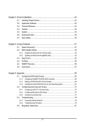
... BIOS with the @BIOS Utility 53 4-3 EasyTune 6...54 4-4 Q-Share...55 4-5 SMART Recovery 56 4-6 Auto Green...57 Chapter 5 Appendix...59 5-1 Configuring SATA Hard Drive(s 59 5-1-1 Configuring GIGABYTE SATA2 SATA Controller 60 5-1-2 Making a SATA RAID/AHCI Driver Diskette 66 5-1-3 Installing the SATA RAID/AHCI Driver and Operating System 67 5-2 Configuring Audio Input and...
... BIOS with the @BIOS Utility 53 4-3 EasyTune 6...54 4-4 Q-Share...55 4-5 SMART Recovery 56 4-6 Auto Green...57 Chapter 5 Appendix...59 5-1 Configuring SATA Hard Drive(s 59 5-1-1 Configuring GIGABYTE SATA2 SATA Controller 60 5-1-2 Making a SATA RAID/AHCI Driver Diskette 66 5-1-3 Installing the SATA RAID/AHCI Driver and Operating System 67 5-2 Configuring Audio Input and...

Manual
Page 6
Box Contents GA-D525TUD or GA-D425TUD motherboard Motherboard driver disk User's Manual One IDE cable One SATA cable I/O Shield • The box contents above are subject to change without notice. • The motherboard image is for reference only and the actual items shall depend on the product package you obtain. Optional Items 2-port USB 2.0 bracket (Part No. 12CR1-1UB030-5*R) 2-port SATA power cable (Part No. 12CF1-2SERPW-0*R) COM port cable (Part No. 12CF1-1CM001-3*R) - 6 - The box contents are for reference only.
Box Contents GA-D525TUD or GA-D425TUD motherboard Motherboard driver disk User's Manual One IDE cable One SATA cable I/O Shield • The box contents above are subject to change without notice. • The motherboard image is for reference only and the actual items shall depend on the product package you obtain. Optional Items 2-port USB 2.0 bracket (Part No. 12CR1-1UB030-5*R) 2-port SATA power cable (Part No. 12CF1-2SERPW-0*R) COM port cable (Part No. 12CF1-1CM001-3*R) - 6 - The box contents are for reference only.
Manual
Page 7
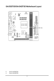
GA-D525TUD/GA-D425TUD Motherboard Layout COM KB_MS iTE IT8720 CI ATX_12V CPU_FAN GA-D525TUD/ GA-D425TUD LPT COMB VGA BAT R_USB Realtek RTL8111E USB_LAN AUDIO F_AUDIO CODEC Intel® Atom™ D525j Intel® Atom™ D425k F_USB1 F_USB2 Intel® NM10 SATA2_0 SATA2_1 B_BIOS M_BIOS PCI DDR3_1 DDR3_2 PWR_LED GSATA2_1GSATA2_0 SYS_FAN IDE ATX F_PANEL GIGABYTE SATA2 j Only for GA-D425TUD. - 7 - k Only for GA-D525TUD.
GA-D525TUD/GA-D425TUD Motherboard Layout COM KB_MS iTE IT8720 CI ATX_12V CPU_FAN GA-D525TUD/ GA-D425TUD LPT COMB VGA BAT R_USB Realtek RTL8111E USB_LAN AUDIO F_AUDIO CODEC Intel® Atom™ D525j Intel® Atom™ D425k F_USB1 F_USB2 Intel® NM10 SATA2_0 SATA2_1 B_BIOS M_BIOS PCI DDR3_1 DDR3_2 PWR_LED GSATA2_1GSATA2_0 SYS_FAN IDE ATX F_PANEL GIGABYTE SATA2 j Only for GA-D425TUD. - 7 - k Only for GA-D525TUD.

Manual
Page 8
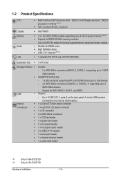
GA-D525TUD/GA-D425TUD Motherboard Block Diagram D-Sub Intel® Atom™ CPU CPU CLK+/- (200 MHz) DDR3 800 MHz Memory DMI Interface LAN RJ45 PCIe CLK (100 MHz) Realtek RTL8111E x1 PCI Express Bus Intel® NM10 x1 2 SATA 3Gb/s ATA-133/100/66/33 IDE Channel GIGABYTE SATA2 PCI Bus Dual BIOS 2 SATA 3Gb/s 8 USB 2.0/1.1 iTE LPC Bus IT8720 LPT Port COM Ports CODEC PS/2 KB/Mouse MIC (Center/Subwoofer Speaker Out) Line-Out (Front Speaker Out) Line-In (Rear Speaker Out) 1 PCI PCI CLK (33 MHz) - 8 -
GA-D525TUD/GA-D425TUD Motherboard Block Diagram D-Sub Intel® Atom™ CPU CPU CLK+/- (200 MHz) DDR3 800 MHz Memory DMI Interface LAN RJ45 PCIe CLK (100 MHz) Realtek RTL8111E x1 PCI Express Bus Intel® NM10 x1 2 SATA 3Gb/s ATA-133/100/66/33 IDE Channel GIGABYTE SATA2 PCI Bus Dual BIOS 2 SATA 3Gb/s 8 USB 2.0/1.1 iTE LPC Bus IT8720 LPT Port COM Ports CODEC PS/2 KB/Mouse MIC (Center/Subwoofer Speaker Out) Line-Out (Front Speaker Out) Line-In (Rear Speaker Out) 1 PCI PCI CLK (33 MHz) - 8 -

Manual
Page 9
These stickers are required for warranty validation. • Always remove the AC power by your hardware components are connected. • To prevent damage to the motherboard, do not allow screws to come in contact with the motherboard circuit or its components. • Make sure there are no leftover screws or metal components placed on the motherboard or within the computer casing. • Do not place the computer system on an uneven surface. • Do not place the computer system in a high-temperature environment. • Turning on the motherboard, make sure they are uncertain ...
These stickers are required for warranty validation. • Always remove the AC power by your hardware components are connected. • To prevent damage to the motherboard, do not allow screws to come in contact with the motherboard circuit or its components. • Make sure there are no leftover screws or metal components placed on the motherboard or within the computer casing. • Do not place the computer system on an uneven surface. • Do not place the computer system in a high-temperature environment. • Turning on the motherboard, make sure they are uncertain ...
Manual
Page 10
k Only for SATA RAID 0, RAID 1, and JBOD USB Chipset: - Support for GA-D425TUD. Hardware Installation - 10 - Up to 8 USB 2.0/1.1 ports (4 on the back panel, 4 via the USB brackets connected to the internal USB ... Slot 1 x PCI slot Storage Interface Chipset: - 2 x SATA 3Gb/s connectors (SATA2_0, SATA2_1) supporting up to 2 SATA 3Gb/s devices GIGABYTE SATA2 chip: - 1 x IDE connector supporting ATA-133/100/66/33 and up to 2 IDE devices - 2 x SATA 3Gb/s connectors (GSATA2_0, GSATA2_1) supporting up to...
k Only for SATA RAID 0, RAID 1, and JBOD USB Chipset: - Support for GA-D425TUD. Hardware Installation - 10 - Up to 8 USB 2.0/1.1 ports (4 on the back panel, 4 via the USB brackets connected to the internal USB ... Slot 1 x PCI slot Storage Interface Chipset: - 2 x SATA 3Gb/s connectors (SATA2_0, SATA2_1) supporting up to 2 SATA 3Gb/s devices GIGABYTE SATA2 chip: - 1 x IDE connector supporting ATA-133/100/66/33 and up to 2 IDE devices - 2 x SATA 3Gb/s connectors (GSATA2_0, GSATA2_1) supporting up to...

Manual
Page 11
Back Panel Connectors I/O Controller w 1 x PS/2 keyboard port w 1 x PS/2 mouse port w 1 x parallel port w 1 x serial port w 1 x D-Sub port w 4 x USB 2.0/1.1 ports w 1 x RJ-45 port w 3 x audio jacks (Line In/Line Out/Microphone) w iTE IT8720 chip Hardware Monitor w w w w BIOS w w w w Unique Features w w w w w w w w w w w System voltage detection CPU temperature detection CPU/System fan speed detection CPU fan speed control 2 x 4 Mbit flash Use of licensed AWARD BIOS Support for DualBIOS™...
Back Panel Connectors I/O Controller w 1 x PS/2 keyboard port w 1 x PS/2 mouse port w 1 x parallel port w 1 x serial port w 1 x D-Sub port w 4 x USB 2.0/1.1 ports w 1 x RJ-45 port w 3 x audio jacks (Line In/Line Out/Microphone) w iTE IT8720 chip Hardware Monitor w w w w BIOS w w w w Unique Features w w w w w w w w w w w System voltage detection CPU temperature detection CPU/System fan speed detection CPU fan speed control 2 x 4 Mbit flash Use of licensed AWARD BIOS Support for DualBIOS™...
Manual
Page 12
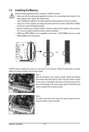
... memory sockets. Step 1: Note the orientation of the memory socket. Place the memory module on the memory and insert it can be used. (Go to GIGABYTE's website for the latest supported memory speeds and memory modules.) • Always turn off the computer and unplug the power cord from the power outlet...
... memory sockets. Step 1: Note the orientation of the memory socket. Place the memory module on the memory and insert it can be used. (Go to GIGABYTE's website for the latest supported memory speeds and memory modules.) • Always turn off the computer and unplug the power cord from the power outlet...

Manual
Page 13
Serial Port Use the serial port to connect devices such as a printer, scanner and etc. D-Sub Port The D-Sub port supports a 15-pin D-Sub connector. RJ-45 LAN Port The Gigabit Ethernet LAN port provides Internet connection at up to connect a PS/2 keyboard. Connection/ Speed LED Activity LED Connection/Speed LED: Activity LED: State Description State Description Orange 1 Gbps data rate Blinking Data transmission or receiving is occurring Green 100 Mbps data rate Off No data transmission or receiving is also called a printer port. Hardware Installation Parallel Port Use the ...
Serial Port Use the serial port to connect devices such as a printer, scanner and etc. D-Sub Port The D-Sub port supports a 15-pin D-Sub connector. RJ-45 LAN Port The Gigabit Ethernet LAN port provides Internet connection at up to connect a PS/2 keyboard. Connection/ Speed LED Activity LED Connection/Speed LED: Activity LED: State Description State Description Orange 1 Gbps data rate Blinking Data transmission or receiving is occurring Green 100 Mbps data rate Off No data transmission or receiving is also called a printer port. Hardware Installation Parallel Port Use the ...

Manual
Page 14
Use this jack. Mic In Jack (Pink) The default Mic in Chapter 5, "Configuring 2/4/5.1/7.1-Channel Audio." Refer to the instructions on setting up a 2/4/5.1/7.1-channel audio configuration in jack. Line Out Jack (Green) The default line out jack. Hardware Installation - 14 - Microphones must be used to this audio jack for line in jack. Use this audio jack for a headphone or 2-channel speaker. This jack can be connected to connect front speakers in a 4/5.1/7.1-channel audio configuration. Line In Jack (Blue) The default line in devices such as an optical drive, walkman, etc....
Use this jack. Mic In Jack (Pink) The default Mic in Chapter 5, "Configuring 2/4/5.1/7.1-Channel Audio." Refer to the instructions on setting up a 2/4/5.1/7.1-channel audio configuration in jack. Line Out Jack (Green) The default line out jack. Hardware Installation - 14 - Microphones must be used to this audio jack for line in jack. Use this audio jack for a headphone or 2-channel speaker. This jack can be connected to connect front speakers in a 4/5.1/7.1-channel audio configuration. Line In Jack (Blue) The default line in devices such as an optical drive, walkman, etc....

Manual
Page 15
Hardware Installation Unplug the power cord from the power outlet to prevent damage to the devices. • After installing the device and before connecting external devices: • First make sure the device cable has been securely attached to the connector on the computer, make sure your devices are compliant with the connectors you wish to connect. • Before installing the devices, be sure to turn off the devices and your computer. 1-5 Internal Connectors 14 1 3 84 2 13 9 11 5 10 12 6 7 1) ATX_12V 2) ATX 3) CPU_FAN 4) SYS_FAN 5) IDE 6) SATA2_0/1 7) GSATA2_0/1 8) ...
Hardware Installation Unplug the power cord from the power outlet to prevent damage to the devices. • After installing the device and before connecting external devices: • First make sure the device cable has been securely attached to the connector on the computer, make sure your devices are compliant with the connectors you wish to connect. • Before installing the devices, be sure to turn off the devices and your computer. 1-5 Internal Connectors 14 1 3 84 2 13 9 11 5 10 12 6 7 1) ATX_12V 2) ATX 3) CPU_FAN 4) SYS_FAN 5) IDE 6) SATA2_0/1 7) GSATA2_0/1 8) ...

Manual
Page 16
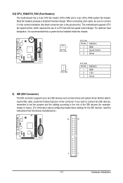
The power connector possesses a foolproof design. The 12V power connector mainly supplies power to the power connector in the correct orientation. Connect the power supply cable to the CPU. If the 12V power connector is turned off and all the components on the motherboard. 1/2) ATX_12V/ATX (2x2 12V Power Connector and 2x10 Main Power Connector) With the use of the power connector, the power supply can supply enough stable power to all devices are properly installed. Before connecting the power connector, first make sure the power supply is not connected, the computer will not ...
The power connector possesses a foolproof design. The 12V power connector mainly supplies power to the power connector in the correct orientation. Connect the power supply cable to the CPU. If the 12V power connector is turned off and all the components on the motherboard. 1/2) ATX_12V/ATX (2x2 12V Power Connector and 2x10 Main Power Connector) With the use of the power connector, the power supply can supply enough stable power to all devices are properly installed. Before connecting the power connector, first make sure the power supply is not connected, the computer will not ...
Manual
Page 17
For optimum heat dissipation, it is the ground wire). Before attaching the IDE cable, locate the foolproof groove on the connector. The motherboard supports CPU fan speed control, which requires the use of the IDE devices (for example, master or slave). (For information about configuring master/slave settings for the IDE devices, read the instructions from the device manufacturers.) 40 39 2 1 - 17 - Hardware Installation If you wish to connect two IDE devices, remember to set the jumpers and the cabling according to the role of a CPU fan with fan speed control design. 3/4) ...
For optimum heat dissipation, it is the ground wire). Before attaching the IDE cable, locate the foolproof groove on the connector. The motherboard supports CPU fan speed control, which requires the use of the IDE devices (for example, master or slave). (For information about configuring master/slave settings for the IDE devices, read the instructions from the device manufacturers.) 40 39 2 1 - 17 - Hardware Installation If you wish to connect two IDE devices, remember to set the jumpers and the cabling according to the role of a CPU fan with fan speed control design. 3/4) ...

Manual
Page 18
...) The SATA connectors conform to SATA 3Gb/s standard and are compatible with SATA 1.5Gb/s standard. Hardware Installation - 18 - The GIGABYTE SATA2 controller supports RAID 0, RAID 1, and JBOD. Each SATA connector supports a single SATA device. 1 SATA2_1 SATA2_0 DEBUG PORT Pin No. 1 2 3 4 5 6 7 Definition GND TXP TXN GND ...
...) The SATA connectors conform to SATA 3Gb/s standard and are compatible with SATA 1.5Gb/s standard. Hardware Installation - 18 - The GIGABYTE SATA2 controller supports RAID 0, RAID 1, and JBOD. Each SATA connector supports a single SATA device. 1 SATA2_1 SATA2_0 DEBUG PORT Pin No. 1 2 3 4 5 6 7 Definition GND TXP TXN GND ...

Manual
Page 19
8) PWR_LED (System Power LED Header) This header can be used to connect a system power LED on when the system is operating. The LED is off when the system is in S3/S4 sleep state or powered off . Pin No. Replace the battery when the battery voltage drops to a low level, or the CMOS values may not be accurate or may clear the CMOS values by yourself or uncertain about the battery model. • When installing the battery, note the orientation of the positive side (+) and the negative side (-) of the battery holder, making them short for one . Replace the battery. 4. System ...
8) PWR_LED (System Power LED Header) This header can be used to connect a system power LED on when the system is operating. The LED is off when the system is in S3/S4 sleep state or powered off . Pin No. Replace the battery when the battery voltage drops to a low level, or the CMOS values may not be accurate or may clear the CMOS values by yourself or uncertain about the battery model. • When installing the battery, note the orientation of the positive side (+) and the negative side (-) of the battery holder, making them short for one . Replace the battery. 4. System ...

Manual
Page 20
The LED is off when the system is operating. Press the reset switch to restart the computer if the computer freezes and fails to the pin assignments below. When connecting your system using the power switch (refer to Chapter 2, "BIOS Setup," "Power Management Setup," for more information). • HD (Hard Drive Activity LED) Connects to the hard drive activity LED on when the hard drive is in S3/S4 sleep S3/S4/S5 Off state or powered off your chassis front panel module to this header according to perform a normal restart. • NC: No connection. Note the positive and ...
The LED is off when the system is operating. Press the reset switch to restart the computer if the computer freezes and fails to the pin assignments below. When connecting your system using the power switch (refer to Chapter 2, "BIOS Setup," "Power Management Setup," for more information). • HD (Hard Drive Activity LED) Connects to the hard drive activity LED on when the hard drive is in S3/S4 sleep S3/S4/S5 Off state or powered off your chassis front panel module to this header according to perform a normal restart. • NC: No connection. Note the positive and ...

Manual
Page 21
Incorrect connection between the module connector and the motherboard header will be sure to turn off your computer and unplug the power cord from the power outlet to prevent damage to activate AC'97 functionality via an optional USB bracket. Definition For AC'97 Front Panel Audio: Pin No. 11) F_AUDIO (Front Panel Audio Header) The front panel audio header supports Intel High Definition audio (HD) and AC'97 audio. Definition 1 2 1 MIC2_L 1 MIC 2 GND 2 GND 9 10 3 MIC2_R 4 -ACZ_DET 3 MIC Power 4 NC 5 LINE2_R 5 Line Out (R) 6 GND 6 NC 7 FAUDIO_JD 7 NC 8 No Pin 8...
Incorrect connection between the module connector and the motherboard header will be sure to turn off your computer and unplug the power cord from the power outlet to prevent damage to activate AC'97 functionality via an optional USB bracket. Definition For AC'97 Front Panel Audio: Pin No. 11) F_AUDIO (Front Panel Audio Header) The front panel audio header supports Intel High Definition audio (HD) and AC'97 audio. Definition 1 2 1 MIC2_L 1 MIC 2 GND 2 GND 9 10 3 MIC2_R 4 -ACZ_DET 3 MIC Power 4 NC 5 LINE2_R 5 Line Out (R) 6 GND 6 NC 7 FAUDIO_JD 7 NC 8 No Pin 8...