
Manual
Page 7
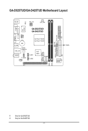
GA-D525TUD/GA-D425TUD Motherboard Layout COM KB_MS iTE IT8720 CI ATX_12V CPU_FAN GA-D525TUD/ GA-D425TUD LPT COMB VGA BAT R_USB Realtek RTL8111E USB_LAN AUDIO F_AUDIO CODEC Intel® Atom™ D525j Intel® Atom™ D425k F_USB1 F_USB2 Intel® NM10 SATA2_0 SATA2_1 B_BIOS M_BIOS PCI DDR3_1 DDR3_2 PWR_LED GSATA2_1GSATA2_0 SYS_FAN IDE ATX F_PANEL GIGABYTE SATA2 j Only for GA-D425TUD. - 7 - k Only for GA-D525TUD.
GA-D525TUD/GA-D425TUD Motherboard Layout COM KB_MS iTE IT8720 CI ATX_12V CPU_FAN GA-D525TUD/ GA-D425TUD LPT COMB VGA BAT R_USB Realtek RTL8111E USB_LAN AUDIO F_AUDIO CODEC Intel® Atom™ D525j Intel® Atom™ D425k F_USB1 F_USB2 Intel® NM10 SATA2_0 SATA2_1 B_BIOS M_BIOS PCI DDR3_1 DDR3_2 PWR_LED GSATA2_1GSATA2_0 SYS_FAN IDE ATX F_PANEL GIGABYTE SATA2 j Only for GA-D425TUD. - 7 - k Only for GA-D525TUD.

Manual
Page 8
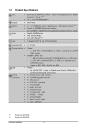
GA-D525TUD/GA-D425TUD Motherboard Block Diagram D-Sub Intel® Atom™ CPU CPU CLK+/- (200 MHz) DDR3 800 MHz Memory DMI Interface LAN RJ45 PCIe CLK (100 MHz) Realtek RTL8111E x1 PCI Express Bus Intel® NM10 x1 2 SATA 3Gb/s ATA-133/100/66/33 IDE Channel GIGABYTE SATA2 PCI Bus Dual BIOS 2 SATA 3Gb/s 8 USB 2.0/1.1 iTE LPC Bus IT8720 LPT Port COM Ports CODEC PS/2 KB/Mouse MIC (Center/Subwoofer Speaker Out) Line-Out (Front Speaker Out) Line-In (Rear Speaker Out) 1 PCI PCI CLK (33 MHz) - 8 -
GA-D525TUD/GA-D425TUD Motherboard Block Diagram D-Sub Intel® Atom™ CPU CPU CLK+/- (200 MHz) DDR3 800 MHz Memory DMI Interface LAN RJ45 PCIe CLK (100 MHz) Realtek RTL8111E x1 PCI Express Bus Intel® NM10 x1 2 SATA 3Gb/s ATA-133/100/66/33 IDE Channel GIGABYTE SATA2 PCI Bus Dual BIOS 2 SATA 3Gb/s 8 USB 2.0/1.1 iTE LPC Bus IT8720 LPT Port COM Ports CODEC PS/2 KB/Mouse MIC (Center/Subwoofer Speaker Out) Line-Out (Front Speaker Out) Line-In (Rear Speaker Out) 1 PCI PCI CLK (33 MHz) - 8 -
Manual
Page 10
...GA-D425TUD. 1-2 Product Specifications CPU Chipset Memory Audio LAN Built in with an Intel® Dual-core Atom™ D525j/ Intel® Single-core Atom™ D425k processor (1.8 GHz) (Note 1) 1M L2 cachej/512K L2 cachek Intel® NM10... Chipset: - 2 x SATA 3Gb/s connectors (SATA2_0, SATA2_1) supporting up to 2 SATA 3Gb/s devices GIGABYTE SATA2 chip: - 1 x IDE connector supporting ATA-133/100/66/33 and up to 2 IDE devices - 2 x ...
...GA-D425TUD. 1-2 Product Specifications CPU Chipset Memory Audio LAN Built in with an Intel® Dual-core Atom™ D525j/ Intel® Single-core Atom™ D425k processor (1.8 GHz) (Note 1) 1M L2 cachej/512K L2 cachek Intel® NM10... Chipset: - 2 x SATA 3Gb/s connectors (SATA2_0, SATA2_1) supporting up to 2 SATA 3Gb/s devices GIGABYTE SATA2 chip: - 1 x IDE connector supporting ATA-133/100/66/33 and up to 2 IDE devices - 2 x ...

Manual
Page 18
...to SATA 3Gb/s standard and are compatible with SATA 1.5Gb/s standard. A RAID 0 or RAID 1 configuration requires at least two hard drives. The GIGABYTE SATA2 controller supports RAID 0, RAID 1, and JBOD. Each SATA connector supports a single SATA device. Definition 1 GND GSATA2_0 2 TXP 3 TXN 4...2 3 4 5 6 7 Definition GND TXP TXN GND RXN RXP GND 7 DEBUG PORT 7) GSATA2_0/1 (SATA 3Gb/s Connectors, Controlled by NM10 Chipset) The SATA connectors conform to Chapter 5, "Configuring SATA Hard Drive(s)," for instructions on configuring a RAID array. 1 Pin No. Hardware Installation - 18 ...
...to SATA 3Gb/s standard and are compatible with SATA 1.5Gb/s standard. A RAID 0 or RAID 1 configuration requires at least two hard drives. The GIGABYTE SATA2 controller supports RAID 0, RAID 1, and JBOD. Each SATA connector supports a single SATA device. Definition 1 GND GSATA2_0 2 TXP 3 TXN 4...2 3 4 5 6 7 Definition GND TXP TXN GND RXN RXP GND 7 DEBUG PORT 7) GSATA2_0/1 (SATA 3Gb/s Connectors, Controlled by NM10 Chipset) The SATA connectors conform to Chapter 5, "Configuring SATA Hard Drive(s)," for instructions on configuring a RAID array. 1 Pin No. Hardware Installation - 18 ...
Manual
Page 33
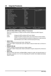
... F10: Save F6: Fail-Safe Defaults ESC: Exit F1: General Help F7: Optimized Defaults SATA AHCI Mode (NM10 Chipset, SATA2_0/1 Connectors) Allows you to decide whether to configure the SATA controllers integrated in the NM10 Chipset to Disabled. Azalia Codec Enables or disables the onboard audio function. (Default: Auto) If you wish...
... F10: Save F6: Fail-Safe Defaults ESC: Exit F1: General Help F7: Optimized Defaults SATA AHCI Mode (NM10 Chipset, SATA2_0/1 Connectors) Allows you to decide whether to configure the SATA controllers integrated in the NM10 Chipset to Disabled. Azalia Codec Enables or disables the onboard audio function. (Default: Auto) If you wish...