Manual
Page 4
Table of Contents GA-8I915G Pro Motherboard Layout 6 Block Diagram ...7 Chapter 1 Hardware Installation 9 1-1 Considerations Priorto Installation 9 1-2 Feature Summary 10 1-3 Installation of the CPU and Heatsink 12 1-3-1 Installation of the CPU 12 1-3-2 Installation of the Heatsink 13 1-4 Installation of Memory 14 1-5 Installexpansion cards 16 1-6 I/O Back Panel Introduction 17 1-7 ConnectorsIntroduction 18 Chapter 2 BIOS Setup 29 The Main ...
Table of Contents GA-8I915G Pro Motherboard Layout 6 Block Diagram ...7 Chapter 1 Hardware Installation 9 1-1 Considerations Priorto Installation 9 1-2 Feature Summary 10 1-3 Installation of the CPU and Heatsink 12 1-3-1 Installation of the CPU 12 1-3-2 Installation of the Heatsink 13 1-4 Installation of Memory 14 1-5 Installexpansion cards 16 1-6 I/O Back Panel Introduction 17 1-7 ConnectorsIntroduction 18 Chapter 2 BIOS Setup 29 The Main ...

Manual
Page 7
Block Diagram VGA LGA775 Pr oce ss or CPU CLK+ /-(2 00/1 33M H z) P CI-E CL K (100M Hz) 3 PCI E xpressx 1 Ports P CI-E CL K (100M Hz) PCI Express x16 PCI Express x1 Bus PCI Bus Marvell TSB43AB23 ...
Block Diagram VGA LGA775 Pr oce ss or CPU CLK+ /-(2 00/1 33M H z) P CI-E CL K (100M Hz) 3 PCI E xpressx 1 Ports P CI-E CL K (100M Hz) PCI Express x16 PCI Express x1 Bus PCI Bus Marvell TSB43AB23 ...

Manual
Page 9
... to installing the electronic components, please have a problem related to wear an electrostatic discharge (ESD) cuff when handling electronic components (CPU, RAM). 4. Instances of an antistatic pad or within the computer casing. 6. Damage due to improper installation. 4. Damage due to...5. Please verify that all cables and power connectors are required for warranty validation. 2. Hardware Installation Thus, prior to be an unofficial Gigabyte product. - 9 - Prior to use exceeding the permitted parameters. 6. These stickers are connected. 4. Damage as physical harm to ...
... to installing the electronic components, please have a problem related to wear an electrostatic discharge (ESD) cuff when handling electronic components (CPU, RAM). 4. Instances of an antistatic pad or within the computer casing. 6. Damage due to improper installation. 4. Damage due to...5. Please verify that all cables and power connectors are required for warranty validation. 2. Hardware Installation Thus, prior to be an unofficial Gigabyte product. - 9 - Prior to use exceeding the permitted parameters. 6. These stickers are connected. 4. Damage as physical harm to ...

Manual
Page 10
Center/Subwoofer Speaker Out ; GA-8I915G Pro Motherboard - 10 - For example, 4 GB of 2 FDD devices w 4 Serial ATA connections w 1 parallel port supporting Normal/EPP/ECP mode w 1 VGA port, onboard COMA connection w 8 USB 2.0/1.1 ports... w 1 RJ 45 port w C-Media 9880 CODEC (UAJ) w Supports Jack Sensing function w Supports 2 / 4 / 5.1 / 7.1 channel audio w Supports Line In ; Back Surround Speaker Out ; English 1-2 Feature Summary CPU Ch ip se t Mem ory Slo ts IDE Connections FDD Connections Onboard SATA Peripherals Onboard LAN Onboard Audio w Supports the latest Intel® Pentium®...
Center/Subwoofer Speaker Out ; GA-8I915G Pro Motherboard - 10 - For example, 4 GB of 2 FDD devices w 4 Serial ATA connections w 1 parallel port supporting Normal/EPP/ECP mode w 1 VGA port, onboard COMA connection w 8 USB 2.0/1.1 ports... w 1 RJ 45 port w C-Media 9880 CODEC (UAJ) w Supports Jack Sensing function w Supports 2 / 4 / 5.1 / 7.1 channel audio w Supports Line In ; Back Surround Speaker Out ; English 1-2 Feature Summary CPU Ch ip se t Mem ory Slo ts IDE Connections FDD Connections Onboard SATA Peripherals Onboard LAN Onboard Audio w Supports the latest Intel® Pentium®...

Manual
Page 11
English I/O Control Hardware Monitor BIOS Additional Features Overclocking Form Factor w IT8712 w CPU / System / Power fan speed detection w CPU temperature detection w System voltage detection w CPU / System / Power fan failure warning w CPU Smart FAN Control w Use of licensed AWARD BIOS w Supports Dual BIOS/Q-Flash w Supports @BIOS w Supports EasyTune w Over Voltage via BIOS (CPU/DDR/PCI-E) w Over Clock via BIOS (CPU/DDR) w ATX form factor; 30.5cm x 24.4cm - 11 - Hardware Installation
English I/O Control Hardware Monitor BIOS Additional Features Overclocking Form Factor w IT8712 w CPU / System / Power fan speed detection w CPU temperature detection w System voltage detection w CPU / System / Power fan failure warning w CPU Smart FAN Control w Use of licensed AWARD BIOS w Supports Dual BIOS/Q-Flash w Supports @BIOS w Supports EasyTune w Over Voltage via BIOS (CPU/DDR/PCI-E) w Over Clock via BIOS (CPU/DDR) w ATX form factor; 30.5cm x 24.4cm - 11 - Hardware Installation

Manual
Page 12
...it does not meet the required standards for your computer system requires all gold color ed triangl e located on the CPU socket. HT functionality requirement content : Enabling the functionality of Hyper-Threading Technology for the peripherals. OS: An operation system ...e the pl astic covering on the edge of the CPU may occur. 5. Please make sure that has optimizations for HT Technology 1-3-1 Installation of the CPU Metal Lever Fig. 1 Gently lift the metal lever located on the CPU prior to the CPU during installation.) GA-8I915G Pro Motherboard - 12 - BIOS: A BIOS that supports...
...it does not meet the required standards for your computer system requires all gold color ed triangl e located on the CPU socket. HT functionality requirement content : Enabling the functionality of Hyper-Threading Technology for the peripherals. OS: An operation system ...e the pl astic covering on the edge of the CPU may occur. 5. Please make sure that has optimizations for HT Technology 1-3-1 Installation of the CPU Metal Lever Fig. 1 Gently lift the metal lever located on the CPU prior to the CPU during installation.) GA-8I915G Pro Motherboard - 12 - BIOS: A BIOS that supports...

Manual
Page 13
... paste be used for Intel boxed fan) Fig. 3 Place the heatsink atop the CPU and m ake sure the push pins aim to the CPU as the picture, the installation is only for heat dissipation or using extreme care when... direction of arrow is to rem ove the heatsink, on the contrary, is to the CPU fan header located on the m other board. If the push pin is inserted as a result of hardening of ...the installed CPU. Fig. 6 Finally, please attach the power connector of m otherboard after installing. The heatsink may...
... paste be used for Intel boxed fan) Fig. 3 Place the heatsink atop the CPU and m ake sure the push pins aim to the CPU as the picture, the installation is only for heat dissipation or using extreme care when... direction of arrow is to rem ove the heatsink, on the contrary, is to the CPU fan header located on the m other board. If the push pin is inserted as a result of hardening of ...the installed CPU. Fig. 6 Finally, please attach the power connector of m otherboard after installing. The heatsink may...

Manual
Page 19
... GND 18 GND 19 GND 20 -5V 21 VCC 22 VCC 23 VCC 24 GND - 19 - The ATX_12V power connector mainly supplies power to the CPU. Ifa power supply is used that does not provide the required power, the result can withstand high power consumption be used (300W or greater). Hardware...
... GND 18 GND 19 GND 20 -5V 21 VCC 22 VCC 23 VCC 24 GND - 19 - The ATX_12V power connector mainly supplies power to the CPU. Ifa power supply is used that does not provide the required power, the result can withstand high power consumption be used (300W or greater). Hardware...
Manual
Page 20
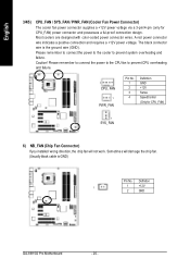
The black connector wire is GND) Pin No. Sometimes will not work. Please remember to connect the power to the cooler to prevent CPU overheating and failure. 1 CPU_ FAN 1 PWR_ FAN Pin No. 1 2 3 4 Definition GND +12V Sense SpeedControl (Onlyfor CPU_FAN) 1 SYS_ ...(Usually black cable is the ground wire (GND). Caution! Please remember to connect the power to the CPU fan to prevent system overheating and fa ilur e. Definition 1 1 +12V 2 GND GA-8I915G Pro Motherboard - 20 - Most coolers are designed with color-coded power connector wires. English 3/4/5) CPU_FAN / ...
The black connector wire is GND) Pin No. Sometimes will not work. Please remember to connect the power to the cooler to prevent CPU overheating and failure. 1 CPU_ FAN 1 PWR_ FAN Pin No. 1 2 3 4 Definition GND +12V Sense SpeedControl (Onlyfor CPU_FAN) 1 SYS_ ...(Usually black cable is the ground wire (GND). Caution! Please remember to connect the power to the CPU fan to prevent system overheating and fa ilur e. Definition 1 1 +12V 2 GND GA-8I915G Pro Motherboard - 20 - Most coolers are designed with color-coded power connector wires. English 3/4/5) CPU_FAN / ...
Manual
Page 30
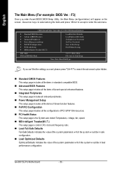
If y ou can't findthe setting y ou w ant, please press "Ctrl+F1" to accept or enter the sub-menu. GA-8I915G Pro Motherboard - 30 - I .T.) This setup page is the Sy stem auto detect Temperature, v oltage, fan, speed. Flash Load Fail-Safe Defaults Load ... all onboard peripherals. n Integrated Peripherals This setup page includes all theitems in standard compatible BIOS. n PC Health Status This setup page is control CPU clock and frequency ratio. n Load Fail -Safe Defaults Fail-Safe Defaults indicates the v alue of PCI &PnP ISA resources. English The Main Menu...
If y ou can't findthe setting y ou w ant, please press "Ctrl+F1" to accept or enter the sub-menu. GA-8I915G Pro Motherboard - 30 - I .T.) This setup page is the Sy stem auto detect Temperature, v oltage, fan, speed. Flash Load Fail-Safe Defaults Load ... all onboard peripherals. n Integrated Peripherals This setup page includes all theitems in standard compatible BIOS. n PC Health Status This setup page is control CPU clock and frequency ratio. n Load Fail -Safe Defaults Fail-Safe Defaults indicates the v alue of PCI &PnP ISA resources. English The Main Menu...

Manual
Page 33
... Test) of floppy disk driv eA or driv e B that used. - 33 - Total Memory This item display s the memory s ize that has been installed in the CPU 's memory address map. None No floppy driv e installed 360K, 5.25" 5.25inch PC-ty pe standard drive; 360Kby te capacity . 1.2M, 5.25" 5.25inch AT-ty pe...
... Test) of floppy disk driv eA or driv e B that used. - 33 - Total Memory This item display s the memory s ize that has been installed in the CPU 's memory address map. None No floppy driv e installed 360K, 5.25" 5.25inch PC-ty pe standard drive; 360Kby te capacity . 1.2M, 5.25" 5.25inch AT-ty pe...
Manual
Page 34
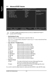
...rity First Boot De vice Second Bo ot Device [Press Enter] [Floppy ] [Hard Disk] Item Help Menu Level} Third Boo t Device Pass word Check # CPU H y per-Thre ading [CDROM] [Se t up w hen y ou install the Intel® Pentium® 4 processor w ithHT Technology. Hard Disk Selecty.../ Second / Third Boot Device Floppy Select y our boot dev ice priority by USB-FDD. LS120 Selecty our boot dev ice priority by CDROM. GA-8I915G Pro Motherboard - 34 - CDROM Selecty our bootdev ice priority by LS120. ZIP Select y our boot dev ice priority by USB-CDROM. USB-CDROM Select...
...rity First Boot De vice Second Bo ot Device [Press Enter] [Floppy ] [Hard Disk] Item Help Menu Level} Third Boo t Device Pass word Check # CPU H y per-Thre ading [CDROM] [Se t up w hen y ou install the Intel® Pentium® 4 processor w ithHT Technology. Hard Disk Selecty.../ Second / Third Boot Device Floppy Select y our boot dev ice priority by USB-FDD. LS120 Selecty our boot dev ice priority by CDROM. GA-8I915G Pro Motherboard - 34 - CDROM Selecty our bootdev ice priority by LS120. ZIP Select y our boot dev ice priority by USB-CDROM. USB-CDROM Select...

Manual
Page 35
... On-chip frame buffer size to 8MB. (Default v alue) 16MB 32MB Set On-chip frame buffer size to 32MB. - 35 - BIOS Setup English CPU Hyper-Threading Enab led Enables CPU Hy per Threading. Limit CPUID Max. to 3 Enab led Limit CPUID Max imum v alue to 3 w hen use older OS like NT4. (Default... v alue) Disabled Disables CPUID Limit for operating sy stem w ith multi processors mode supported. (Default v alue) Disabled Disables CPU Hy per Threading Feature. Set On-chip frame buffer size to 16MB.
... On-chip frame buffer size to 8MB. (Default v alue) 16MB 32MB Set On-chip frame buffer size to 32MB. - 35 - BIOS Setup English CPU Hyper-Threading Enab led Enables CPU Hy per Threading. Limit CPUID Max. to 3 Enab led Limit CPUID Max imum v alue to 3 w hen use older OS like NT4. (Default... v alue) Disabled Disables CPUID Limit for operating sy stem w ith multi processors mode supported. (Default v alue) Disabled Disables CPU Hy per Threading Feature. Set On-chip frame buffer size to 16MB.

Manual
Page 42
...alue) Fan w arning function enable. Enab led Enable CPU Smart Fan control function. (Default v alue) a. When the CPU temperature is lower than 40 degrees Celsius, CPU fanw ill be disable. Whenthe CPU temperature is higher than 65 degree. English 2-6 PC Health... / +12V Detect sy stem's v oltage status automatically . CPU Sm art FAN Control Disabled Disable thi s function. b. Current CPU Temperature Detect CPU temperature automatically . GA-8I915G Pro Motherboard - 42 - The speed of CPU fan w ill increase linearly depand onthe temperature if the temperature ...
...alue) Fan w arning function enable. Enab led Enable CPU Smart Fan control function. (Default v alue) a. When the CPU temperature is lower than 40 degrees Celsius, CPU fanw ill be disable. Whenthe CPU temperature is higher than 65 degree. English 2-6 PC Health... / +12V Detect sy stem's v oltage status automatically . CPU Sm art FAN Control Disabled Disable thi s function. b. Current CPU Temperature Detect CPU temperature automatically . GA-8I915G Pro Motherboard - 42 - The speed of CPU fan w ill increase linearly depand onthe temperature if the temperature ...

Manual
Page 43
...MB In telligent Tweaker(M. Full T hrust Set C .I .A.2 to Full Thrust. (Automatically increase CPU frequency (15%, 17%, 19%) by C PU loading. CPU Clock Ratio This setup option w ill automatically assign by C PU loading. Turbo Set C.I .A.2 to Turbo... and automatic ally adjus t CPU computing pow er to 4pin. 2-7 MB Intelligent Tweaker(M.I .A.2 to Cruise. (Automatically increas e CPU frequency (3%,5%,7%) by CPU loading. Spo rts Set C .I .A.2 to Sports. (Automatically increas e CPU frequency (5%,7%,9%) by CPU loading. I.T.) CPU Clock Ratio C.I . BIOS Setup...
...MB In telligent Tweaker(M. Full T hrust Set C .I .A.2 to Full Thrust. (Automatically increase CPU frequency (15%, 17%, 19%) by C PU loading. CPU Clock Ratio This setup option w ill automatically assign by C PU loading. Turbo Set C.I .A.2 to Turbo... and automatic ally adjus t CPU computing pow er to 4pin. 2-7 MB Intelligent Tweaker(M.I .A.2 to Cruise. (Automatically increas e CPU frequency (3%,5%,7%) by CPU loading. Spo rts Set C .I .A.2 to Sports. (Automatically increas e CPU frequency (5%,7%,9%) by CPU loading. I.T.) CPU Clock Ratio C.I . BIOS Setup...

Manual
Page 44
... Ov erVoltage Control to +0.2V. Normal CPU Vcore Display y our CPU Vcore Voltage. Disabled Disable CPU Host Clock Control. (Default v alue) Enabled Enable CPU Host Clock Control. Incorrect using itmay cause y our sy stem broken. GA-8I915G Pro Motherboard - 44 - Incorrect using itmay ...cause y our sy stem broken. English CPU Host Clock Control Pleasenote thatif y our system is set "CPU Host Frequency " to200MHz. Memory Frequency For Wrong frequency may...
... Ov erVoltage Control to +0.2V. Normal CPU Vcore Display y our CPU Vcore Voltage. Disabled Disable CPU Host Clock Control. (Default v alue) Enabled Enable CPU Host Clock Control. Incorrect using itmay cause y our sy stem broken. GA-8I915G Pro Motherboard - 44 - Incorrect using itmay ...cause y our sy stem broken. English CPU Host Clock Control Pleasenote thatif y our system is set "CPU Host Frequency " to200MHz. Memory Frequency For Wrong frequency may...

Manual
Page 53
... (M.I.T.) allows user to withstand varying current levels and changes, the U-Plus D.P.S. C.I.A.2 (CPU Intelligent Accelerator 2) GIGABYTE CPU Intelligent Accelerator 2(C.I .B. 2 features. Download Center Download Center allows users to enabled Gigabyte's unique C.I.A. 2 and M.I .A. 2) is no longer need to open up errors ...the new Memory Intelligent Booster 2 (M.I .B.2 (Memory Intelligent Booster 2) Built on the U-Plus D.P.S. Instead, S.O.S. With GIGABYTE's proprietary S.O.S. As well, 4 blue LED's are able to factory default settings. These characteristics make it the ideal ...
... (M.I.T.) allows user to withstand varying current levels and changes, the U-Plus D.P.S. C.I.A.2 (CPU Intelligent Accelerator 2) GIGABYTE CPU Intelligent Accelerator 2(C.I .B. 2 features. Download Center Download Center allows users to enabled Gigabyte's unique C.I.A. 2 and M.I .A. 2) is no longer need to open up errors ...the new Memory Intelligent Booster 2 (M.I .B.2 (Memory Intelligent Booster 2) Built on the U-Plus D.P.S. Instead, S.O.S. With GIGABYTE's proprietary S.O.S. As well, 4 blue LED's are able to factory default settings. These characteristics make it the ideal ...


