
Manual
Page 4
Table of Contents GA-8I865GVM-775/GA-8I865GVMF-775 Motherboard Layout 6 Block Diagram ...7 Chapter 1 Hardware Installation 9 1-1 Considerations Prior to Installation 9 1-2 Feature Summary 10 1-3 Installation of the CPU and Heatsink 11 1-3-1 Installation of the CPU 11 1-3-2 Installation of the Heatsink 12 1-4 Installation of Memory 13 1-5 Installation of Expansion Cards 15 1-6 I/O Back Panel Introduction 16 1-7 Connectors Introduction 17 Chapter 2 BIOS...
Table of Contents GA-8I865GVM-775/GA-8I865GVMF-775 Motherboard Layout 6 Block Diagram ...7 Chapter 1 Hardware Installation 9 1-1 Considerations Prior to Installation 9 1-2 Feature Summary 10 1-3 Installation of the CPU and Heatsink 11 1-3-1 Installation of the CPU 11 1-3-2 Installation of the Heatsink 12 1-4 Installation of Memory 13 1-5 Installation of Expansion Cards 15 1-6 I/O Back Panel Introduction 16 1-7 Connectors Introduction 17 Chapter 2 BIOS...

Manual
Page 9
... result of the motherboard or any hardware, please first carefully read the information in the user manual. 3. Damage due to be an unofficial Gigabyte product. - 9 - Hardware Installation To prevent damage to the motherboard, please do not allow screws to come in contact with the motherboard circuit... on top of Non-Warranty 1. If you the power supply is bestto wear an electrostatic discharge (ESD) cuff when handling electronic components (CPU, RAM). 4. When handling the motherboard, avoid touching any installation steps or have these items on an uneven surface. 7. Before using the...
... result of the motherboard or any hardware, please first carefully read the information in the user manual. 3. Damage due to be an unofficial Gigabyte product. - 9 - Hardware Installation To prevent damage to the motherboard, please do not allow screws to come in contact with the motherboard circuit... on top of Non-Warranty 1. If you the power supply is bestto wear an electrostatic discharge (ESD) cuff when handling electronic components (CPU, RAM). 4. When handling the motherboard, avoid touching any installation steps or have these items on an uneven surface. 7. Before using the...
Manual
Page 10
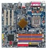
... Connections Onboard SATA Peripherals Onboard LAN Onboard Audio I/O Control Hardware Monitor BIOS Additional Features Form Factor w GA-8I865GVM-775 or GA-8I865GVMF-775 w Supports the latest Intel® Pentium® 4 LGA775 CPU w Supports 800/533MHz FSB w L2 cache varies with CPU w Northbridge: Intel® 865GV Chipset w Southbridge: Intel® ICH5 w 4 DDR DIMM memory slots (supports up to...
... Connections Onboard SATA Peripherals Onboard LAN Onboard Audio I/O Control Hardware Monitor BIOS Additional Features Form Factor w GA-8I865GVM-775 or GA-8I865GVMF-775 w Supports the latest Intel® Pentium® 4 LGA775 CPU w Supports 800/533MHz FSB w L2 cache varies with CPU w Northbridge: Intel® 865GV Chipset w Southbridge: Intel® ICH5 w 4 DDR DIMM memory slots (supports up to...

Manual
Page 11
... to the upright position. If you wish to system use, otherwise overheating and permanent damage of the CPU may occur. 5. If you install the CPU in the wrong direction, the CPU will not insert properly. Chipset: An Intel® Chipset that supports HT Technology and has it enabled...the indented corner of heat sink paste between your computer system requires all gold colored triangle located on the CPU socket. It is not recommended that the motherboard supports the CPU. 2. CPU: An Intel® Pentium 4 Processor with the following platform components: - Fig. 3 Notice the sm ...
... to the upright position. If you wish to system use, otherwise overheating and permanent damage of the CPU may occur. 5. If you install the CPU in the wrong direction, the CPU will not insert properly. Chipset: An Intel® Chipset that supports HT Technology and has it enabled...the indented corner of heat sink paste between your computer system requires all gold colored triangle located on the CPU socket. It is not recommended that the motherboard supports the CPU. 2. CPU: An Intel® Pentium 4 Processor with the following platform components: - Fig. 3 Notice the sm ...
Manual
Page 12
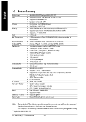
...is suggested that either thermal tape rather than heat sink paste be used for detailed installation instructions, please refer to the CPU as the picture, the installation is complete. GA-8I865GVM(F)-775 Motherboard - 12 - If the push pin is only for Intel boxed fan) Fig. 3 Place the heatsink atop ...the CPU and m ake sure the pus h pi ns ai m to the CPU fan header located on the surface of the installed CPU. The heatsink may adhere ...
...is suggested that either thermal tape rather than heat sink paste be used for detailed installation instructions, please refer to the CPU as the picture, the installation is complete. GA-8I865GVM(F)-775 Motherboard - 12 - If the push pin is only for Intel boxed fan) Fig. 3 Place the heatsink atop ...the CPU and m ake sure the pus h pi ns ai m to the CPU fan header located on the surface of the installed CPU. The heatsink may adhere ...
Manual
Page 18
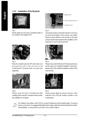
... is unable to handle the system voltage requirements. Please use of the power connector, the power supply can supply enough stable power to the CPU. Please remove the sticker on the motherboard and connect tightly. Before connecting the power connector, please make sure that can lead to an unstable... 3.3V 14 -12V 15 GND 16 PS_ON(softOn/Off) 17 GND 18 GND 19 GND 20 -5 V 21 VCC 22 VCC 23 VCC 24 GND GA-8I865GVM(F)-775 Motherboard - 18 - It is used that does not provide the required power, the result can withstand high power consumption be used (300W or greater). ...
... is unable to handle the system voltage requirements. Please use of the power connector, the power supply can supply enough stable power to the CPU. Please remove the sticker on the motherboard and connect tightly. Before connecting the power connector, please make sure that can lead to an unstable... 3.3V 14 -12V 15 GND 16 PS_ON(softOn/Off) 17 GND 18 GND 19 GND 20 -5 V 21 VCC 22 VCC 23 VCC 24 GND GA-8I865GVM(F)-775 Motherboard - 18 - It is used that does not provide the required power, the result can withstand high power consumption be used (300W or greater). ...

Manual
Page 19
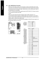
... design. Please connect the red power connector wire to prevent system overheating and failure. Please remember to connect the power to the CPU fan to connect the FDD cable while the other end of FDD drives supported are designed with color-coded power connector wires. Hardware... Installation The black connector wire is used to prevent CPU overheating and failure. 1 C PU _FAN 1 SYS_FAN Pin No. 1 2 3 4 Definition GND +12V Sense Speed Control (Onlyfor CPU_FAN) 5) FDD (FDD Connector)...
... design. Please connect the red power connector wire to prevent system overheating and failure. Please remember to connect the power to the CPU fan to connect the FDD cable while the other end of FDD drives supported are designed with color-coded power connector wires. Hardware... Installation The black connector wire is used to prevent CPU overheating and failure. 1 C PU _FAN 1 SYS_FAN Pin No. 1 2 3 4 Definition GND +12V Sense Speed Control (Onlyfor CPU_FAN) 5) FDD (FDD Connector)...
Manual
Page 28
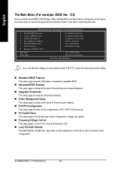
...findthe setting y ou w ant, please press "Ctrl+F1" to accept or enter thesub-menu. n PC Health Status This setup page is control CPU clock and frequency ratio. CMOS Setup Utility -Cop y right (C) 198 4-2004 Award Software } Stan dard CM OS Features } Advanc ed BIOSFe atures... v alue of Green function features. n Standard CMOS Features This setup page includes all the configurations of Aw ard special enhanced features. GA-8I865GVM(F)- 775 Motherboard - 28 - n PnP/PCI Configuration This setup page includes all theitems in safe configu ration. n Frequency/ Voltage Control This...
...findthe setting y ou w ant, please press "Ctrl+F1" to accept or enter thesub-menu. n PC Health Status This setup page is control CPU clock and frequency ratio. CMOS Setup Utility -Cop y right (C) 198 4-2004 Award Software } Stan dard CM OS Features } Advanc ed BIOSFe atures... v alue of Green function features. n Standard CMOS Features This setup page includes all the configurations of Aw ard special enhanced features. GA-8I865GVM(F)- 775 Motherboard - 28 - n PnP/PCI Configuration This setup page includes all theitems in safe configu ration. n Frequency/ Voltage Control This...

Manual
Page 33
...-Threading Enab led Enables CPU Hy per Threading. Limit CPUID Max. On-Chip Frame Buffer Size 1MB Set on-chip frame buffer size to 1MB. 4MB Set on-chip frame ... to 3 w hen use older OS like NT4. (Default v alue) Disables CPUID Limit for operating sy stem w ith multi processors mode supported. (Default v alue) Disabled Disables CPU Hy per Threading Feature. Please note that this feature is only working for w indow s XP. to 3 Enab led Disabled Limit CPUID Max imum v alue to...
...-Threading Enab led Enables CPU Hy per Threading. Limit CPUID Max. On-Chip Frame Buffer Size 1MB Set on-chip frame buffer size to 1MB. 4MB Set on-chip frame ... to 3 w hen use older OS like NT4. (Default v alue) Disables CPUID Limit for operating sy stem w ith multi processors mode supported. (Default v alue) Disabled Disables CPU Hy per Threading Feature. Please note that this feature is only working for w indow s XP. to 3 Enab led Disabled Limit CPUID Max imum v alue to...

Manual
Page 39
... Setup Utility -Cop y right (C) 198 4-2004 Award Software PCH ealth Status CurrentCPU Temperature CurrentSy stem Temperature Vcore +3.3V +5V +12V DDR25V Curren t CPU FAN Speed Curr ent SYST EM FAN Speed 50oC 32oC 1.35V 3.28V 5.17V 11.84V 2.39V 3308 RPM 0 RPM Item Help Menu Level} higf:...us Values +/-/PU/P D:Value F10: Save F6:Fail-Sa fe Defaults ESC: Ex it F1:Gene ralHelp F7:Op timized De faults Current CPU/System Temperature Detect CPU/Sy stem temperature automatically . Current Voltage(V) V core / +3.3V / +5V / +12V / DDR25V Detect sy stem's v oltage status automatically . ...
... Setup Utility -Cop y right (C) 198 4-2004 Award Software PCH ealth Status CurrentCPU Temperature CurrentSy stem Temperature Vcore +3.3V +5V +12V DDR25V Curren t CPU FAN Speed Curr ent SYST EM FAN Speed 50oC 32oC 1.35V 3.28V 5.17V 11.84V 2.39V 3308 RPM 0 RPM Item Help Menu Level} higf:...us Values +/-/PU/P D:Value F10: Save F6:Fail-Sa fe Defaults ESC: Ex it F1:Gene ralHelp F7:Op timized De faults Current CPU/System Temperature Detect CPU/Sy stem temperature automatically . Current Voltage(V) V core / +3.3V / +5V / +12V / DDR25V Detect sy stem's v oltage status automatically . ...
Manual
Page 40
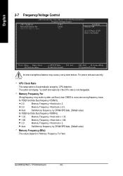
... Incorrect usingthese features may make sy stem can't boot, clear CMOS to overcome wrong frequency issue. Auto Set Memory frequency by CPU detection. GA-8I865GVM(F)- 775 Motherboard - 40 - For pow er end-user useonly . CPU Clock Ratio This setup option w ill automatically assign by DRAM SPD data. (Default v alue) Mem ory Frequency (Mhz) The values...
... Incorrect usingthese features may make sy stem can't boot, clear CMOS to overcome wrong frequency issue. Auto Set Memory frequency by CPU detection. GA-8I865GVM(F)- 775 Motherboard - 40 - For pow er end-user useonly . CPU Clock Ratio This setup option w ill automatically assign by DRAM SPD data. (Default v alue) Mem ory Frequency (Mhz) The values...


