
Manual
Page 1
GA-5YASV-RH Xeon® Processor Motherboard USER'S MANUAL Xeon® Processor Motherboard Rev. 1001 * The WEEE marking on the product indicates this product must not be disposed of with user's other household waste and must be handed over to a designated collection point for the recycling of waste electrical and electronic equipment!! * The WEEE marking applies only in European Union's member states.
GA-5YASV-RH Xeon® Processor Motherboard USER'S MANUAL Xeon® Processor Motherboard Rev. 1001 * The WEEE marking on the product indicates this product must not be disposed of with user's other household waste and must be handed over to a designated collection point for the recycling of waste electrical and electronic equipment!! * The WEEE marking applies only in European Union's member states.

Manual
Page 2
... Table of Content Item Checklist 4 WARNING 4 Chapter 1 Introduction 5 1.1 Features Summary 5 1.2 GA-5YASV-RH Motherboard Components 8 Chapter 2 Hardware Installation Process 10 2-1: Installing Processor and CPU Haet Sink 10 2-1-1: Installing CPU ...10 2-1-2: Installing Cooling Fan 11 2-2: Install Memory Modules 12 2-3: ...
... Table of Content Item Checklist 4 WARNING 4 Chapter 1 Introduction 5 1.1 Features Summary 5 1.2 GA-5YASV-RH Motherboard Components 8 Chapter 2 Hardware Installation Process 10 2-1: Installing Processor and CPU Haet Sink 10 2-1-1: Installing CPU ...10 2-1-2: Installing Cooling Fan 11 2-2: Install Memory Modules 12 2-3: ...

Manual
Page 3
English Table of Content Chapter 4 INTEL RAID BIOS Configuration 67 Chapter 5 Appendix 72 3
English Table of Content Chapter 4 INTEL RAID BIOS Configuration 67 Chapter 5 Appendix 72 3

Manual
Page 4
... may damage the board or cause board malfunctioning. 4 Be careful, don't let the screw contact any printed circuit write or parts on the inside. 2. English GA-5YASV-RH Motherboard Item Checklist The GA-5YASV-RH motherboard IDE (ATA133 ) cable x 1 / Floppy cable x 1 CD for motherboard driver & utility USB cable x 1 Serial ATA cable x 6 I/O Shield Kit SATA Power cable...
... may damage the board or cause board malfunctioning. 4 Be careful, don't let the screw contact any printed circuit write or parts on the inside. 2. English GA-5YASV-RH Motherboard Item Checklist The GA-5YASV-RH motherboard IDE (ATA133 ) cable x 1 / Floppy cable x 1 CD for motherboard driver & utility USB cable x 1 Serial ATA cable x 6 I/O Shield Kit SATA Power cable...

Manual
Page 5
Chapter 1 Introduction Introduction 1.1 Features Summary Form Factor CPU Chipset Memory I /O Supports 2 PCI slots 32-Bit/33MHz (5V) Supports 1 PCI-Express x8 slot Supports 1 PCI-Express x8 slot (at x1 bandwidth) Built in Intel® ICH9R with Software RAID 0,1,10, 5 (Windows Only) Optional LSI SW RAID 0/1/10 Supports 6 SATA 3.0 Gb/s connectors XGI Volari Z9s 32MB DDR2 1 ATA 133 connector 1 Floppyport supports 360K, 720K,1.2M, 1.44M and 2.88M bytes. 2 PS/2 connectors 1 Parallel port supports Normal/EPP/ECP mode 2 Serial port (COM, 1 by cable) 6 x USB 2.0 (4 by cable) 1 VGA connector 2 x ...
Chapter 1 Introduction Introduction 1.1 Features Summary Form Factor CPU Chipset Memory I /O Supports 2 PCI slots 32-Bit/33MHz (5V) Supports 1 PCI-Express x8 slot Supports 1 PCI-Express x8 slot (at x1 bandwidth) Built in Intel® ICH9R with Software RAID 0,1,10, 5 (Windows Only) Optional LSI SW RAID 0/1/10 Supports 6 SATA 3.0 Gb/s connectors XGI Volari Z9s 32MB DDR2 1 ATA 133 connector 1 Floppyport supports 360K, 720K,1.2M, 1.44M and 2.88M bytes. 2 PS/2 connectors 1 Parallel port supports Normal/EPP/ECP mode 2 Serial port (COM, 1 by cable) 6 x USB 2.0 (4 by cable) 1 VGA connector 2 x ...

Manual
Page 6
English GA-5YASV-RH Motherboard Hardware Monitor On-Board LAN BIOS Special Features Additional Features Enhanced features with CPU Vcore, 1.2V reference, VCC3 (3.3V) , VBAT3V, +5VSB, CPU Temperature, and ...
English GA-5YASV-RH Motherboard Hardware Monitor On-Board LAN BIOS Special Features Additional Features Enhanced features with CPU Vcore, 1.2V reference, VCC3 (3.3V) , VBAT3V, +5VSB, CPU Temperature, and ...

Manual
Page 7
Introduction 7
Introduction 7

Manual
Page 8
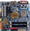
SAMSUNG DDR2 6. IDE cable connector 10. SATA2 Connector 17. Front Panle connector 25. DDR2B1 32. English GA-5YASV-RH Motherboard 1.2 GA-5YASV-RH Motherboard Components 1. XGI Volari Z9s 5. SATA1 Connector 16. SATA5 Connector 20. Front fan cable connector 23. Rear fan cable connector 24. PCI-E x8 Slot 28. ...
SAMSUNG DDR2 6. IDE cable connector 10. SATA2 Connector 17. Front Panle connector 25. DDR2B1 32. English GA-5YASV-RH Motherboard 1.2 GA-5YASV-RH Motherboard Components 1. XGI Volari Z9s 5. SATA1 Connector 16. SATA5 Connector 20. Front fan cable connector 23. Rear fan cable connector 24. PCI-E x8 Slot 28. ...

Manual
Page 9
Introduction 34 35 36 23 37 4 57 33 33 21 25 26 27 28 8 40 11 20 24 1 2 12 13 3 38 22 29 30 31 32 9 6 10 39 19 18 17 16 15 14 9
Introduction 34 35 36 23 37 4 57 33 33 21 25 26 27 28 8 40 11 20 24 1 2 12 13 3 38 22 29 30 31 32 9 6 10 39 19 18 17 16 15 14 9

Manual
Page 10
... push the metal lever back into the socket. 3. Please change the insert orientation. 2-1-1: Installing CPU Step 1 Raise the metal locking lever on the socket. English GA-5YASV-RH Motherboard Chapter 2 Hardware Installation Process 2-1: Installing Processor and CPU Haet Sink Before installing the processor and cooling fan, adhere to the following cautions: 1. Step 3 Lift...
... push the metal lever back into the socket. 3. Please change the insert orientation. 2-1-1: Installing CPU Step 1 Raise the metal locking lever on the socket. English GA-5YASV-RH Motherboard Chapter 2 Hardware Installation Process 2-1: Installing Processor and CPU Haet Sink Before installing the processor and cooling fan, adhere to the following cautions: 1. Step 3 Lift...

Manual
Page 11
Step 3 Secure the cooing fan with screws. Step 2 Place the cooling fan on the heat sink. Step 4 Connect processor fan can cable to the processor socket. 2-1-2: Installing Cooling Fan Hardware Installation Process Step 1 Attach the heat sink clip to the processor fanconnector 11
Step 3 Secure the cooing fan with screws. Step 2 Place the cooling fan on the heat sink. Step 4 Connect processor fan can cable to the processor socket. 2-1-2: Installing Cooling Fan Hardware Installation Process Step 1 Attach the heat sink clip to the processor fanconnector 11

Manual
Page 12
It supports Dual Channels Technology. The BIOS will automatically detects memory type and size during system boot. For detail DIMM installation, please refer to the following instructions. English GA-5YASV-RH Motherboard 2-2: Install Memory Modules Before installing the processor and heatsink, adhere to the following warning: When DIMM LED is ON, do not install/remove DIMM from socket. Channel B 12 Channel A GA-5YASV-RH has 4 dual inline memory module (DIMM) sokcets.
It supports Dual Channels Technology. The BIOS will automatically detects memory type and size during system boot. For detail DIMM installation, please refer to the following instructions. English GA-5YASV-RH Motherboard 2-2: Install Memory Modules Before installing the processor and heatsink, adhere to the following warning: When DIMM LED is ON, do not install/remove DIMM from socket. Channel B 12 Channel A GA-5YASV-RH has 4 dual inline memory module (DIMM) sokcets.

Manual
Page 13
Unlock a DIMM socket by pressing the retaining clips outwards.Aling a DIMM on the socket such that the notch on each socket and the same DIMM size. 4. Reverse the installation steps if you to remove the DIMM module. 13 NOTE!! Supported DIMM Module Type Size 256MB 512MB 1GB Organization 8MB x 8 x 4 bks 16MB x 4 x 4bks 16MB x 8 x 4bks 32MB x 4 x 4bks 32MB x 8 x 4bks 64MB x 4 x 4bks Hardware Installation Process RAM Chips/DIMM 8 16 8 16 8 16 Installation Steps: 1. We recommened you want to populate the same device size on the DIMM exactly match the notch in place. Firmly insert ...
Unlock a DIMM socket by pressing the retaining clips outwards.Aling a DIMM on the socket such that the notch on each socket and the same DIMM size. 4. Reverse the installation steps if you to remove the DIMM module. 13 NOTE!! Supported DIMM Module Type Size 256MB 512MB 1GB Organization 8MB x 8 x 4 bks 16MB x 4 x 4bks 16MB x 8 x 4bks 32MB x 4 x 4bks 32MB x 8 x 4bks 64MB x 4 x 4bks Hardware Installation Process RAM Chips/DIMM 8 16 8 16 8 16 Installation Steps: 1. We recommened you want to populate the same device size on the DIMM exactly match the notch in place. Firmly insert ...

Manual
Page 14
English GA-5YASV-RH Motherboard 2-3: Connect ribbon cables, cabinet wires, and power supply 2-3-1 : I/O Back Panel Introduction 14
English GA-5YASV-RH Motherboard 2-3: Connect ribbon cables, cabinet wires, and power supply 2-3-1 : I/O Back Panel Introduction 14

Manual
Page 15
have a standard USB interface. LAN LED Description LED2 (Green/Yellow) LED1 (Green) Name LED1 LED2 Color Green Green Green Green Yellow Yellow Condition ON BLINK OFF OFF OFF ON BLINK ON BLINK Description LAN Link / no Access LAN Access Idle 10Mbps connection Port identification with 10 Mbps connection 100Mbps connection Port identification with 100Mbps connection 1Gbps connection Port identification with 1Gbps connection 15 Also make sure your OS or device(s) vendors. If your OS supports USB controller. For more information please contact your device(s) such as USB keyboard, ...
have a standard USB interface. LAN LED Description LED2 (Green/Yellow) LED1 (Green) Name LED1 LED2 Color Green Green Green Green Yellow Yellow Condition ON BLINK OFF OFF OFF ON BLINK ON BLINK Description LAN Link / no Access LAN Access Idle 10Mbps connection Port identification with 10 Mbps connection 100Mbps connection Port identification with 100Mbps connection 1Gbps connection Port identification with 1Gbps connection 15 Also make sure your OS or device(s) vendors. If your OS supports USB controller. For more information please contact your device(s) such as USB keyboard, ...

Manual
Page 16
SATA 0 (SATA Connector) 6. F_USB1 (USB cable connector) 13. IDE1 (IDE cable connector) 4. SATA 1 (SATA cable connector) 7. SATA 5 (SATA cable connector) 11. FRONT_FAN 18. English GA-5YASV-RH Motherboard 2-4: Connectors Introduction 18 16 2 15 11 20 12 13 14 10 8 6 17 9 7 19 5 4 3 1 1. SATA 3 (SATA cable connector) 9. SGPIO1 15. CPU_FAN 16. COM2 12. ATX2 3. ...
SATA 0 (SATA Connector) 6. F_USB1 (USB cable connector) 13. IDE1 (IDE cable connector) 4. SATA 1 (SATA cable connector) 7. SATA 5 (SATA cable connector) 11. FRONT_FAN 18. English GA-5YASV-RH Motherboard 2-4: Connectors Introduction 18 16 2 15 11 20 12 13 14 10 8 6 17 9 7 19 5 4 3 1 1. SATA 3 (SATA cable connector) 9. SGPIO1 15. CPU_FAN 16. COM2 12. ATX2 3. ...

Manual
Page 17
1) ATX1 (24-pin ATX power connector) 24 13 12 1 AC power cord should only be connected to your power supply unit after ATX power cable and other related devices are firmly connected to the mainboard. 2 ) ATX2 (4-pin ATX power connector/12V) Connector Introduction PIN No. 1 2 3 4 5 6 7 8 9 10 11 12 13 14 15 16 17 18 19 20 21 22 23 24 Definition +3.3V +3.3V GND +5V GND +5V GND POK 5VSB +12V +12V +3.3V +3.3V -12V GND PSON GND GND GND -5V +5V +5V +5V GND 42 31 Pin No. 1 2 3 4 Definition GND GND +12V +12V This connector (ATX +12V) is used only for CPU Core Voltage. 17
1) ATX1 (24-pin ATX power connector) 24 13 12 1 AC power cord should only be connected to your power supply unit after ATX power cable and other related devices are firmly connected to the mainboard. 2 ) ATX2 (4-pin ATX power connector/12V) Connector Introduction PIN No. 1 2 3 4 5 6 7 8 9 10 11 12 13 14 15 16 17 18 19 20 21 22 23 24 Definition +3.3V +3.3V GND +5V GND +5V GND POK 5VSB +12V +12V +3.3V +3.3V -12V GND PSON GND GND GND -5V +5V +5V +5V GND 42 31 Pin No. 1 2 3 4 Definition GND GND +12V +12V This connector (ATX +12V) is used only for CPU Core Voltage. 17

Manual
Page 18
English GA-5YASV-RH Motherboard 3 ) IDE1 (IDE Connector) Please connect first harddisk to FDD. The red stripe of the ribbon cable must be the same side with the Pin1. 1 33 2 34 18 It supports 720K,1.2M,1.44M and 2.88Mbytes floppy disk types. The red stripe of the ribbon cable must be the same side with the Pin1. 39 40 1 2 4 ) FDC1 (Floppy Connector) Please connect the floppy drive ribbon cables to IDE1.
English GA-5YASV-RH Motherboard 3 ) IDE1 (IDE Connector) Please connect first harddisk to FDD. The red stripe of the ribbon cable must be the same side with the Pin1. 1 33 2 34 18 It supports 720K,1.2M,1.44M and 2.88Mbytes floppy disk types. The red stripe of the ribbon cable must be the same side with the Pin1. 39 40 1 2 4 ) FDC1 (Floppy Connector) Please connect the floppy drive ribbon cables to IDE1.

Manual
Page 19
Connector Introduction 5/ 6/ 7/ 89/10 ) SATA 0~5 (Serial ATA cable connectors) You can connect the Serial ATA device to this connector, it provides you high speed transfer rates (3.0Gb/sec). 1 Pin No. Definition 1 GND 2 TXP 3 TXN 4 GND 5 RXN 6 RXP 7 7 GND 11 ) COM2 (Serial port connector) 12 9 10 Pin No. 1 2 3 4 5 6 7 8 9 10 Definition DCDSIN2 SOUT2 DTR2GND DSR2RTS2CTS2RI2NC 19
Connector Introduction 5/ 6/ 7/ 89/10 ) SATA 0~5 (Serial ATA cable connectors) You can connect the Serial ATA device to this connector, it provides you high speed transfer rates (3.0Gb/sec). 1 Pin No. Definition 1 GND 2 TXP 3 TXN 4 GND 5 RXN 6 RXP 7 7 GND 11 ) COM2 (Serial port connector) 12 9 10 Pin No. 1 2 3 4 5 6 7 8 9 10 Definition DCDSIN2 SOUT2 DTR2GND DSR2RTS2CTS2RI2NC 19

Manual
Page 20
... is a storage controller located inside a server, desktop, rack or workstation computer that interfaces with the polarity of the 4 signals, 3 are driven by the backplane. English GA-5YASV-RH Motherboard 12/ 13 ) F_USB1/2 (USB cable connectors) Be careful with Hard disk drives (HDDs) to work or even damage it.
... is a storage controller located inside a server, desktop, rack or workstation computer that interfaces with the polarity of the 4 signals, 3 are driven by the backplane. English GA-5YASV-RH Motherboard 12/ 13 ) F_USB1/2 (USB cable connectors) Be careful with Hard disk drives (HDDs) to work or even damage it.