
Manual
Page 2
... Table of Content Item Checklist 4 WARNING 4 Chapter 1 Introduction 5 1.1 Features Summary 5 1.2 GA-5YASV-RH Motherboard Components 8 Chapter 2 Hardware Installation Process 10 2-1: Installing Processor and CPU Haet Sink 10 2-1-1: Installing CPU ...10 2-1-2: Installing Cooling Fan 11 2-2: Install Memory Modules 12 2-3: Connect ribbon cables, cabinet wires, and power supply 14 2-3-1 : I/O Back Panel Introduction 14 2-4: Connectors Introduction 16 2-5: ...
... Table of Content Item Checklist 4 WARNING 4 Chapter 1 Introduction 5 1.1 Features Summary 5 1.2 GA-5YASV-RH Motherboard Components 8 Chapter 2 Hardware Installation Process 10 2-1: Installing Processor and CPU Haet Sink 10 2-1-1: Installing CPU ...10 2-1-2: Installing Cooling Fan 11 2-2: Install Memory Modules 12 2-3: Connect ribbon cables, cabinet wires, and power supply 14 2-3-1 : I/O Back Panel Introduction 14 2-4: Connectors Introduction 16 2-5: ...

Manual
Page 5
Chapter 1 Introduction Introduction 1.1 Features Summary Form Factor CPU Chipset Memory I /O Supports 2 PCI slots 32-Bit/33MHz (5V) Supports 1 PCI-Express x8 slot Supports 1 PCI-Express x8 slot (at x1 bandwidth) Built in LGA ...
Chapter 1 Introduction Introduction 1.1 Features Summary Form Factor CPU Chipset Memory I /O Supports 2 PCI slots 32-Bit/33MHz (5V) Supports 1 PCI-Express x8 slot Supports 1 PCI-Express x8 slot (at x1 bandwidth) Built in LGA ...

Manual
Page 6
English GA-5YASV-RH Motherboard Hardware Monitor On-Board LAN BIOS Special Features Additional Features Enhanced features with CPU Vcore, 1.2V reference, VCC3 (3.3V) , VBAT3V, +5VSB, CPU Temperature, and System Temperature Values viewing CPU/Power/System Fan Revolution Detect CPU shutdown when overheat System Voltage Detect Intel® 82566DM & 82573LGbE controllers Supports dual Gigabit LAN ports I/O Acceleration Technology...
English GA-5YASV-RH Motherboard Hardware Monitor On-Board LAN BIOS Special Features Additional Features Enhanced features with CPU Vcore, 1.2V reference, VCC3 (3.3V) , VBAT3V, +5VSB, CPU Temperature, and System Temperature Values viewing CPU/Power/System Fan Revolution Detect CPU shutdown when overheat System Voltage Detect Intel® 82566DM & 82573LGbE controllers Supports dual Gigabit LAN ports I/O Acceleration Technology...

Manual
Page 8
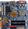
.... Intel 3200 3. SAMSUNG DDR2 6. Intel 82573LGbE 8. IDE cable connector 10. Front USB2 Connector 14. DDR2B1 32. DDR2B2 33. COM Port 37. English GA-5YASV-RH Motherboard 1.2 GA-5YASV-RH Motherboard Components 1. Intel ICH9R 4. CPU fan cable connector 21. Front Panle connector 25. PCI-E x8 Slot (x1 bandwidth) 29. VGA Port 35. SATA1 Connector 16. DDR2A2 31. PS...
.... Intel 3200 3. SAMSUNG DDR2 6. Intel 82573LGbE 8. IDE cable connector 10. Front USB2 Connector 14. DDR2B1 32. DDR2B2 33. COM Port 37. English GA-5YASV-RH Motherboard 1.2 GA-5YASV-RH Motherboard Components 1. Intel ICH9R 4. CPU fan cable connector 21. Front Panle connector 25. PCI-E x8 Slot (x1 bandwidth) 29. VGA Port 35. SATA1 Connector 16. DDR2A2 31. PS...

Manual
Page 10
... lever on the socket. Please make sure the CPU type is properly placed, please replace the metal cover and push the metal lever back into the socket. 3. Step 4 Insert the CPU with the correct orientation. English GA-5YASV-RH Motherboard Chapter 2 Hardware Installation Process 2-1: Installing Processor and CPU Haet Sink Before installing the processor and cooling...
... lever on the socket. Please make sure the CPU type is properly placed, please replace the metal cover and push the metal lever back into the socket. 3. Step 4 Insert the CPU with the correct orientation. English GA-5YASV-RH Motherboard Chapter 2 Hardware Installation Process 2-1: Installing Processor and CPU Haet Sink Before installing the processor and cooling...

Manual
Page 17
1) ATX1 (24-pin ATX power connector) 24 13 12 1 AC power cord should only be connected to your power supply unit after ATX power cable and other related devices are firmly connected to the mainboard. 2 ) ATX2 (4-pin ATX power connector/12V) Connector Introduction PIN No. 1 2 3 4 5 6 7 8 9 10 11 12 13 14 15 16 17 18 19 20 21 22 23 24 Definition +3.3V +3.3V GND +5V GND +5V GND POK 5VSB +12V +12V +3.3V +3.3V -12V GND PSON GND GND GND -5V +5V +5V +5V GND 42 31 Pin No. 1 2 3 4 Definition GND GND +12V +12V This connector (ATX +12V) is used only for CPU Core Voltage. 17
1) ATX1 (24-pin ATX power connector) 24 13 12 1 AC power cord should only be connected to your power supply unit after ATX power cable and other related devices are firmly connected to the mainboard. 2 ) ATX2 (4-pin ATX power connector/12V) Connector Introduction PIN No. 1 2 3 4 5 6 7 8 9 10 11 12 13 14 15 16 17 18 19 20 21 22 23 24 Definition +3.3V +3.3V GND +5V GND +5V GND POK 5VSB +12V +12V +3.3V +3.3V -12V GND PSON GND GND GND -5V +5V +5V +5V GND 42 31 Pin No. 1 2 3 4 Definition GND GND +12V +12V This connector (ATX +12V) is used only for CPU Core Voltage. 17

Manual
Page 21
... No. 1 2 3 4 Definition GND 12V Sense Control FRONT_FAN 21 These connectors are for system use only. current up to prevent the CPU from running under abnormal condition or damaged by overheating.The CPU fan connector supports Max. Definition 1 GND 1 2 12V 3 Sense 4 Control 16/ 17/18 ) SYS_FAN/ERONT_FAN/REAR_FAN (System fan cable connectors) These...
... No. 1 2 3 4 Definition GND 12V Sense Control FRONT_FAN 21 These connectors are for system use only. current up to prevent the CPU from running under abnormal condition or damaged by overheating.The CPU fan connector supports Max. Definition 1 GND 1 2 12V 3 Sense 4 Control 16/ 17/18 ) SYS_FAN/ERONT_FAN/REAR_FAN (System fan cable connectors) These...

Manual
Page 39
... setting) Disabled Disables C1 Enhanced Mode. 39 Advanced Processor Options BIOS Setup Figure 1-1: Advanced Processor Option Advanced Processor Option This category includes the information of CPU Speed, Processor CPUID, and Processor L2 Cache. C1 Enhanced Mode With enabling C1 Enhanced Mode, all loical processors in the physical processor have entered the...
... setting) Disabled Disables C1 Enhanced Mode. 39 Advanced Processor Options BIOS Setup Figure 1-1: Advanced Processor Option Advanced Processor Option This category includes the information of CPU Speed, Processor CPUID, and Processor L2 Cache. C1 Enhanced Mode With enabling C1 Enhanced Mode, all loical processors in the physical processor have entered the...

Manual
Page 51
Voltage Monitor: DDR1V8, VCC3V3, VCORE, 12V2, 5V Detect system's voltage status automatically. Hardware Monitor BIOS Setup Figure 2-5: Hardware Monitor CPU / Motherboard/ DDR Temperature Display the current CPU temperature, Motherboard, and Ambient temperature. FAN Monitor: CPU Fan/ System Fan/ Front Fan/ Rear Fan (RPM) Display the current CPU and system fAN speed. 51
Voltage Monitor: DDR1V8, VCC3V3, VCORE, 12V2, 5V Detect system's voltage status automatically. Hardware Monitor BIOS Setup Figure 2-5: Hardware Monitor CPU / Motherboard/ DDR Temperature Display the current CPU temperature, Motherboard, and Ambient temperature. FAN Monitor: CPU Fan/ System Fan/ Front Fan/ Rear Fan (RPM) Display the current CPU and system fAN speed. 51

Manual
Page 72
GA-5YASV-RH Motherboard RCehvaispitoenr H5istAoprypendix Appendix : Acronyms Acronyms Meaning ACPI Advanced Configuration and Power Interface APM Advanced Power Management AGP Accelerated Graphics Port AMR Audio Modem Riser ACR Advanced Communications Riser BBS BIOS Boot Specification BIOS Basic Input / Output System CPU Central Processing Unit CMOS Complementary Metal Oxide Semiconductor CRIMM Continuity RIMM CNR Communication...
GA-5YASV-RH Motherboard RCehvaispitoenr H5istAoprypendix Appendix : Acronyms Acronyms Meaning ACPI Advanced Configuration and Power Interface APM Advanced Power Management AGP Accelerated Graphics Port AMR Audio Modem Riser ACR Advanced Communications Riser BBS BIOS Boot Specification BIOS Basic Input / Output System CPU Central Processing Unit CMOS Complementary Metal Oxide Semiconductor CRIMM Continuity RIMM CNR Communication...


