User Manual
Page 5
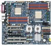
Motherboard GA-2CEWH Motherboard CPU Support Dual Opteron processors (Sledge Hammer) The HyperTransport link of the AMD Opteron processor is capable of Features Form Factor 30.4cm x 33.0cm EATX size form factor, 8 layers PCB. Supports L2/3 Cache with 1MB/2MB Chipset AMD-8132 Bridge HyperTransport PCI-X chipset provides two independent, high-performance PCI-X bus...
Motherboard GA-2CEWH Motherboard CPU Support Dual Opteron processors (Sledge Hammer) The HyperTransport link of the AMD Opteron processor is capable of Features Form Factor 30.4cm x 33.0cm EATX size form factor, 8 layers PCB. Supports L2/3 Cache with 1MB/2MB Chipset AMD-8132 Bridge HyperTransport PCI-X chipset provides two independent, high-performance PCI-X bus...
User Manual
Page 6
GA-2CEWH Motherboard On-Board Peripherals RAID Supported Hardware Monitor Power Managerment Features IEEE1394A Audio On-Board LAN PS/2 Connector BIOS Additional Features 1 Floppy port supports 2 FDD with 360K, 720K,1.2M, 1.44M and 2.88M bytes. 1 Parallel port supports Normal/EPP/ECP mode 1 Serial port (COM) 8 x USB 2.0 2 x RJ45 LAN port 2 x IEEE 1394a 2 x PS/2 Connector Supports.../System Fan Revolution detect CPU/System temperature detect System Voltage Detect Power Management Support Wake-on-LAN (WOL), USB, PCI, mouse Supports ACPI S1/S3/S4/S5 functions TI TSB43AB23 ALC 850 Boradcom BCM 5751T ...
GA-2CEWH Motherboard On-Board Peripherals RAID Supported Hardware Monitor Power Managerment Features IEEE1394A Audio On-Board LAN PS/2 Connector BIOS Additional Features 1 Floppy port supports 2 FDD with 360K, 720K,1.2M, 1.44M and 2.88M bytes. 1 Parallel port supports Normal/EPP/ECP mode 1 Serial port (COM) 8 x USB 2.0 2 x RJ45 LAN port 2 x IEEE 1394a 2 x PS/2 Connector Supports.../System Fan Revolution detect CPU/System temperature detect System Voltage Detect Power Management Support Wake-on-LAN (WOL), USB, PCI, mouse Supports ACPI S1/S3/S4/S5 functions TI TSB43AB23 ALC 850 Boradcom BCM 5751T ...

User Manual
Page 9
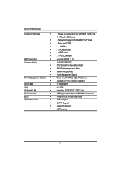
Connect ribbon cables, cabinet wires, and power supply Step 5- Hardware Installation Process Chapter 2 Hardware Installation Process To set up your computer, you must complete the following steps: Step 1- Install the Central Processing Unit (CPU) Step 2- Setup BIOS software Step 6- Install supporting software tools Step 3 Step 2 Step 5 Step 4 Step 1 Step 4 Step 4 Step 1 Step 2 9 Install memory modules Step 3- Install expansion cards Step 4-
Connect ribbon cables, cabinet wires, and power supply Step 5- Hardware Installation Process Chapter 2 Hardware Installation Process To set up your computer, you must complete the following steps: Step 1- Install the Central Processing Unit (CPU) Step 2- Setup BIOS software Step 6- Install supporting software tools Step 3 Step 2 Step 5 Step 4 Step 1 Step 4 Step 4 Step 1 Step 2 9 Install memory modules Step 3- Install expansion cards Step 4-
User Manual
Page 10
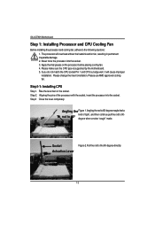
Please change the insert orientation. Socket Figure 2. Please make sure the CPU type is supported by the motherboard. 5. Step 3 Close the lever completely. Apply thermal grease on the socket. Rise the lever bar on the processor before placing cooling fan. 4. ... the pins of tight , and then continue pull the rod to 650 kind of the processor with the socket, insert the processor into the socket. 3. GA-2CEWH Motherboard Step 1: Installing Processor and CPU Cooling Fan Before installing the processor and cooling fan, adhere to the 90-degree directly.
Please change the insert orientation. Socket Figure 2. Please make sure the CPU type is supported by the motherboard. 5. Step 3 Close the lever completely. Apply thermal grease on the socket. Rise the lever bar on the processor before placing cooling fan. 4. ... the pins of tight , and then continue pull the rod to 650 kind of the processor with the socket, insert the processor into the socket. 3. GA-2CEWH Motherboard Step 1: Installing Processor and CPU Cooling Fan Before installing the processor and cooling fan, adhere to the 90-degree directly.
User Manual
Page 12
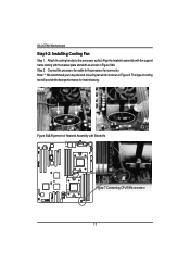
Attach th cooling fan clip to the processor fan connector. Coonect the processor fan cable to the processor scoket. This type of cooling fan which is shown in Figure 5&6. Figure 5&6 Alignment of Heatsink Assembly with the backer plate standoffs as shown in Figure 8. Align the heatsink assembly with the support frame mating with Standoffs Figure 7 Connecting CPU FAN connector 12 Note: ** We recommend you to buy the kind of cooling fan will provide the best performance for heat releasing. GA-2CEWH Motherboard Step1-2: Installing Cooling Fan Step 1. Step 2.
Attach th cooling fan clip to the processor fan connector. Coonect the processor fan cable to the processor scoket. This type of cooling fan which is shown in Figure 5&6. Figure 5&6 Alignment of Heatsink Assembly with the backer plate standoffs as shown in Figure 8. Align the heatsink assembly with the support frame mating with Standoffs Figure 7 Connecting CPU FAN connector 12 Note: ** We recommend you to buy the kind of cooling fan will provide the best performance for heat releasing. GA-2CEWH Motherboard Step1-2: Installing Cooling Fan Step 1. Step 2.
User Manual
Page 14
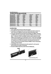
...DIMM 0 and 2 can only be populated in the tables. 4. Reverse the installation steps when you wish to create the 128 bit bus; The processor supports 64-bit mode and 128-bit mode configuration of DIMMs in 64 bit mode are listed in order starting at the farest slotfrom the processor...the DIMMinto the socket until the retaining clips snap back in the socket. Regardless of two DIMMs is required to remove the DIMM module. GA-2CEWH Motherboard Total Memory Sizes With Registered DDR DIMM Devices used on each and the same DIMM size. Installed DIMMs must be madeof two identical ...
...DIMM 0 and 2 can only be populated in the tables. 4. Reverse the installation steps when you wish to create the 128 bit bus; The processor supports 64-bit mode and 128-bit mode configuration of DIMMs in 64 bit mode are listed in order starting at the farest slotfrom the processor...the DIMMinto the socket until the retaining clips snap back in the socket. Regardless of two DIMMs is required to remove the DIMM module. GA-2CEWH Motherboard Total Memory Sizes With Registered DDR DIMM Devices used on each and the same DIMM size. Installed DIMMs must be madeof two identical ...
User Manual
Page 18
... - have a standard USB interface. If your OS or device(s) vendors. LAN LED Description Name Color LAN Green Link/Activity Green - 10/100 LAN Green Speed - GA-2CEWH Motherboard PS/2 Keyboard and PS/2 Mouse Connector To install a PS/2 port keyboard and mouse, plug the mouse to the upper port (green) and the keyboard... to Parallel port ; For more information please contact your OS does not support USB controller, please contact OS vendor for possible patch or driver updated. Also make sure your OS...
... - have a standard USB interface. If your OS or device(s) vendors. LAN LED Description Name Color LAN Green Link/Activity Green - 10/100 LAN Green Speed - GA-2CEWH Motherboard PS/2 Keyboard and PS/2 Mouse Connector To install a PS/2 port keyboard and mouse, plug the mouse to the upper port (green) and the keyboard... to Parallel port ; For more information please contact your OS does not support USB controller, please contact OS vendor for possible patch or driver updated. Also make sure your OS...

User Manual
Page 23
The red stripe of the ribbon cable must be the same side with the Pin1. 12 33 34 23 The red stripe of the ribbon cable must be the same side with the Pin1. 1 2 39 40 E ) FDD1 (Floppy Connector) Please connect the floppy drive ribbon cables to IDE2. It supports 360K,720K,1.2M,1.44M and 2.88Mbytes floppy disk types. Connector Introduction C / D ) IDE 1/2 Please connect first harddisk to IDE1 and connect CDROM to FDD.
The red stripe of the ribbon cable must be the same side with the Pin1. 12 33 34 23 The red stripe of the ribbon cable must be the same side with the Pin1. 1 2 39 40 E ) FDD1 (Floppy Connector) Please connect the floppy drive ribbon cables to IDE2. It supports 360K,720K,1.2M,1.44M and 2.88Mbytes floppy disk types. Connector Introduction C / D ) IDE 1/2 Please connect first harddisk to IDE1 and connect CDROM to FDD.

User Manual
Page 27
Connector Introduction N ) WOL (Wake On LAN Connector) This connector allows the remove servers to manage the system that installed this mainboard via your network adapter which also supports WOL. 1 Pin No. Definition 1 Ring 2 GND 27 Definition 1 +5V SB 2 GND 3 Signal O ) WOR (Wake on Ring Connector) 1 Pin No.
Connector Introduction N ) WOL (Wake On LAN Connector) This connector allows the remove servers to manage the system that installed this mainboard via your network adapter which also supports WOL. 1 Pin No. Definition 1 Ring 2 GND 27 Definition 1 +5V SB 2 GND 3 Signal O ) WOR (Wake on Ring Connector) 1 Pin No.
User Manual
Page 28
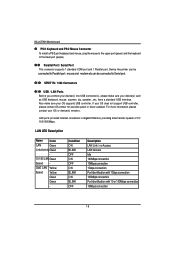
Pin No. To find out if the chassis you are buying support front audio connector, please contact your chassis must remove 5-6, 9-10 Jumper. Definition 1 MIC 10 9 2 GND 3 REF 4 POWER 5 FrontAudio(R) 6 RearAudio(R) 21 7 Reserved 8 No Pin 9 FrontAudio (L) 10 ... have front audio connector. Also please make sure the pin assigment on the cable is the same as the pin assigment on the MB header. GA-2CEWH Motherboard P ) F_Audio (Front Audio connector) If you want to utilize the front audio header, your dealer.
Pin No. To find out if the chassis you are buying support front audio connector, please contact your chassis must remove 5-6, 9-10 Jumper. Definition 1 MIC 10 9 2 GND 3 REF 4 POWER 5 FrontAudio(R) 6 RearAudio(R) 21 7 Reserved 8 No Pin 9 FrontAudio (L) 10 ... have front audio connector. Also please make sure the pin assigment on the cable is the same as the pin assigment on the MB header. GA-2CEWH Motherboard P ) F_Audio (Front Audio connector) If you want to utilize the front audio header, your dealer.

User Manual
Page 31
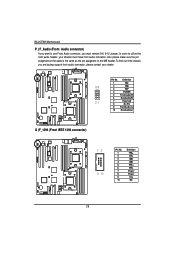
... turn ON the computer. Note: Pin 4 is essential to prevent the CPU from running under abnormal condition or damaged by overheating.The CPU fan connector supports Max. manufacturer's instructions. Definition 1 GND 2 +12V 1 3 Sense 4 Control CPU1_FAN CPU0_FAN 31 current up to erase CMOS... 1.Turn OFF the computer and unplug the power cord...
... turn ON the computer. Note: Pin 4 is essential to prevent the CPU from running under abnormal condition or damaged by overheating.The CPU fan connector supports Max. manufacturer's instructions. Definition 1 GND 2 +12V 1 3 Sense 4 Control CPU1_FAN CPU0_FAN 31 current up to erase CMOS... 1.Turn OFF the computer and unplug the power cord...

User Manual
Page 33
Definition 1 GND 2 12V 3 Sense 4 Control FAN5 4 ) PWR_JP (PS/2 Wake Up Power Source Jumper) 1 1-2 close:support PS2 wake up from S3 (Default) 1 2-3 close: Disable this function 33 Connector Introduction 1 / 2 / 3 ) FAN2 / 4 / 3 (Front Fan / Rear Fam / System FAN) This connector allows you to link with the cooling fan on the system case to lower the system temperature. FAN4 FAN2 1 Pin No.
Definition 1 GND 2 12V 3 Sense 4 Control FAN5 4 ) PWR_JP (PS/2 Wake Up Power Source Jumper) 1 1-2 close:support PS2 wake up from S3 (Default) 1 2-3 close: Disable this function 33 Connector Introduction 1 / 2 / 3 ) FAN2 / 4 / 3 (Front Fan / Rear Fam / System FAN) This connector allows you to link with the cooling fan on the system case to lower the system temperature. FAN4 FAN2 1 Pin No.
User Manual
Page 39
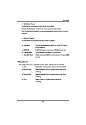
... max imize the IDE data transfer rate. BIOS Setup Multi-Sector Transfer This field displays the information of the device in the specific IDE channel support LBA Mode. Other Select 'Other' if your operating system is not on the item list. This filed displays the DMA mode of Multi-Sector Transfer... Mode. Disabled: The data transfer from and to the device occurs one sector at a time if the device supports it. Installed OS This category allows you use commonly .
... max imize the IDE data transfer rate. BIOS Setup Multi-Sector Transfer This field displays the information of the device in the specific IDE channel support LBA Mode. Other Select 'Other' if your operating system is not on the item list. This filed displays the DMA mode of Multi-Sector Transfer... Mode. Disabled: The data transfer from and to the device occurs one sector at a time if the device supports it. Installed OS This category allows you use commonly .

User Manual
Page 44
GA-2CEWH Motherboard Processor PhoenixTrustedCore(tm) Setup Utility Advanced Processor Item Specific Help CPU0 Type: AMD Optern(tm) Processor 244 CPU0 Speed: 1800Mz CPU0 ID: 0751 CPU0 ... cannot be modified. MPS Version This option allows user to configure the multiprocessor(MP) specification revision level. Some operating system will require 1.1 for compatibility reasons. 1.4 Support MPS Version 1.4 . (Default) 1.1 Support M PS Version 1.1. 44 This displays the installed CPU physical information.
GA-2CEWH Motherboard Processor PhoenixTrustedCore(tm) Setup Utility Advanced Processor Item Specific Help CPU0 Type: AMD Optern(tm) Processor 244 CPU0 Speed: 1800Mz CPU0 ID: 0751 CPU0 ... cannot be modified. MPS Version This option allows user to configure the multiprocessor(MP) specification revision level. Some operating system will require 1.1 for compatibility reasons. 1.4 Support MPS Version 1.4 . (Default) 1.1 Support M PS Version 1.1. 44 This displays the installed CPU physical information.

User Manual
Page 48
Disabled Disable this function. GA-2CEWH Motherboard Chipset Advanced Chipset DRAM Bank Interleaving NODE memory Interleaving ACPI SRAT Table ECC Memory Checking PhoenixTrustedCore(tm) Setup Utility [Auto] [Auto] [Disabled] [Enabled] ... Auto BIOS will automatically detect capability on each node. (Default value) Disabled Disable this function. ECC Memory Checking Enabled All memory modules in the system support parity ECC mode. ACPI SRAT Table Enabled Enable ACPI 2.0 static resources affinity table or NUMA system. (Default value) Disabled Disable this function. (Default value...
Disabled Disable this function. GA-2CEWH Motherboard Chipset Advanced Chipset DRAM Bank Interleaving NODE memory Interleaving ACPI SRAT Table ECC Memory Checking PhoenixTrustedCore(tm) Setup Utility [Auto] [Auto] [Disabled] [Enabled] ... Auto BIOS will automatically detect capability on each node. (Default value) Disabled Disable this function. ECC Memory Checking Enabled All memory modules in the system support parity ECC mode. ACPI SRAT Table Enabled Enable ACPI 2.0 static resources affinity table or NUMA system. (Default value) Disabled Disable this function. (Default value...

User Manual
Page 50
GA-2CEWH Motherboard ATA Controller PhoenixTrustedCore(tm) Setup Utility Advanced ATA Controller Item Specific Help P-ATA Interface [Pata 1/2 + P-ATA 3/4] S-ATA Interface [Enabled] S-ATA Mode [Native] F1: Help .... 50 SATA Interface Enabled Disabled Enable first serial ATA device. SATA Mode Native RAID Serial ATA configured in native mode.Some operating systems do not support native IDE devices. PATA 3/4 Specify the Parallel ATA Channel to PATA 1/2.
GA-2CEWH Motherboard ATA Controller PhoenixTrustedCore(tm) Setup Utility Advanced ATA Controller Item Specific Help P-ATA Interface [Pata 1/2 + P-ATA 3/4] S-ATA Interface [Enabled] S-ATA Mode [Native] F1: Help .... 50 SATA Interface Enabled Disabled Enable first serial ATA device. SATA Mode Native RAID Serial ATA configured in native mode.Some operating systems do not support native IDE devices. PATA 3/4 Specify the Parallel ATA Channel to PATA 1/2.

User Manual
Page 54
... users to enable or disable the USB 2.0 device by setting item to the desired value. GA-2CEWH Motherboard Integrated USB PhoenixTrustedCore(tm) Setup Utility Advanced Integrated USB Item Specific Help Integrated USB 1.1 [Enabled] Integrated USB 2.0 [Enabled] LegacyUSB Support F1: Help Esc: Exit KL: Select Item IJ: Select Menu [Enabled] + -: Change Values F5: Setup...
... users to enable or disable the USB 2.0 device by setting item to the desired value. GA-2CEWH Motherboard Integrated USB PhoenixTrustedCore(tm) Setup Utility Advanced Integrated USB Item Specific Help Integrated USB 1.1 [Enabled] Integrated USB 2.0 [Enabled] LegacyUSB Support F1: Help Esc: Exit KL: Select Item IJ: Select Menu [Enabled] + -: Change Values F5: Setup...

User Manual
Page 57
... I/O Address 378 278 3BC Set IO address to 378. (Default value) Set IO address to 3BC. Set IO address to 278. Set the Interrupt to support bi-directional transfers on the parallel port. EPP Using Parallel port as DMA channel. Interrupt IRQ5 IRQ7 Set the Interrupt to configure parallel port by...
... I/O Address 378 278 3BC Set IO address to 378. (Default value) Set IO address to 3BC. Set IO address to 278. Set the Interrupt to support bi-directional transfers on the parallel port. EPP Using Parallel port as DMA channel. Interrupt IRQ5 IRQ7 Set the Interrupt to configure parallel port by...

User Manual
Page 76
Click "Next". 6. This application contains a set of utilities supporting diagnostic, monitoring, and configuration for this feature to WMI based management applications. Note that presents network adapter information to function properly. This feature will install Broadcom Advanced Server Program. GA-2CEWH Motherboard CUSTOM Setup Ready to install the program. Click "Install" 6. Ready to Install 5. This...
Click "Next". 6. This application contains a set of utilities supporting diagnostic, monitoring, and configuration for this feature to WMI based management applications. Note that presents network adapter information to function properly. This feature will install Broadcom Advanced Server Program. GA-2CEWH Motherboard CUSTOM Setup Ready to install the program. Click "Install" 6. Ready to Install 5. This...

