Quick Specs
Page 1
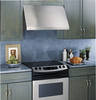
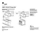
...9' and 10' ceilings 42" min. 52" max. 12 30 18 Hood Installation Height (24" to your Monogram,® GE Profile™ or GE® appliance questions, visit our website at GEAppliances.com or call GE Answer Center® service, 800.626.2000. For cabinets of greater depth, place... material behind hood. Specification Revised 7/09 220956 36 Listed by Underwriters Laboratories For answers to 36") 21 (Standard 8 ft. GE Profile™ 36" Designer Hood Installed above a cooktop (shown with 11 product for 30" Designer hoods JXCHSS-Stainless Chimney Kit 42" min. 12 52" max....
...9' and 10' ceilings 42" min. 52" max. 12 30 18 Hood Installation Height (24" to your Monogram,® GE Profile™ or GE® appliance questions, visit our website at GEAppliances.com or call GE Answer Center® service, 800.626.2000. For cabinets of greater depth, place... material behind hood. Specification Revised 7/09 220956 36 Listed by Underwriters Laboratories For answers to 36") 21 (Standard 8 ft. GE Profile™ 36" Designer Hood Installed above a cooktop (shown with 11 product for 30" Designer hoods JXCHSS-Stainless Chimney Kit 42" min. 12 52" max....

Use and Care Manual
Page 1
LI1P4H 49-80520-2 06-09 JR Vented Range Hoods GEAppliances.com Safety Instructions 2, 3 Operating Instructions Fan Control 4 Light Control 4 Care and Cleaning Grease Filters 5 Hood Lights 6 Stainless Steel Surfaces 5 Installation Instructions . . .7-18 Troubleshooting Tips 19 Consumer Support Consumer Support 24 Owner Registration 21, 22 Warranty 23 Owner's Manual and Installation Instructions JV936 JV966 Write the model and serial numbers here: Model Serial You can find them on a label on the inside of the hood.
LI1P4H 49-80520-2 06-09 JR Vented Range Hoods GEAppliances.com Safety Instructions 2, 3 Operating Instructions Fan Control 4 Light Control 4 Care and Cleaning Grease Filters 5 Hood Lights 6 Stainless Steel Surfaces 5 Installation Instructions . . .7-18 Troubleshooting Tips 19 Consumer Support Consumer Support 24 Owner Registration 21, 22 Warranty 23 Owner's Manual and Installation Instructions JV936 JV966 Write the model and serial numbers here: Model Serial You can find them on a label on the inside of the hood.
Use and Care Manual
Page 3
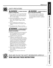
... cutting or drilling into wall or ceiling, do not damage electrical wiring and other servicing should not be referred to accumulate on fan or filter. B. C. C. Installation work and electrical wiring must always be done by the National Fire Protection Association (NFPA), the American Society for the size of fuel burning equipment...
... cutting or drilling into wall or ceiling, do not damage electrical wiring and other servicing should not be referred to accumulate on fan or filter. B. C. C. Installation work and electrical wiring must always be done by the National Fire Protection Association (NFPA), the American Society for the size of fuel burning equipment...
Use and Care Manual
Page 7
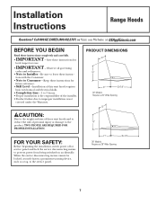
...power off at :GwEwAwpp.GlEiaAnpcpelisa.nccoems.com BEFORE YOU BEGIN Read these vent hoods and to reduce the risk of the installer. • Product failure due to Installer - When the service disconnecting means cannot be locked, securely fasten a prominent warning device, such as a tag, ...Skill Level - Observe all governing codes and ordinances. • Note to improper installation is the responsibility of personal injury or damage to the product, TWO PEOPLE ARE REQUIRED FOR PROPER INSTALLATION. Call 800.GE.CARES (800.432.2737) or Visit our Website at service panel and lock ...
...power off at :GwEwAwpp.GlEiaAnpcpelisa.nccoems.com BEFORE YOU BEGIN Read these vent hoods and to reduce the risk of the installer. • Product failure due to Installer - When the service disconnecting means cannot be locked, securely fasten a prominent warning device, such as a tag, ...Skill Level - Observe all governing codes and ordinances. • Note to improper installation is the responsibility of personal injury or damage to the product, TWO PEOPLE ARE REQUIRED FOR PROPER INSTALLATION. Call 800.GE.CARES (800.432.2737) or Visit our Website at service panel and lock ...

Use and Care Manual
Page 8
...2 Washers 2 Wall Screws Fasteners 4 Phillips Head Screws 2 Phillips Head Decorative Screws 2-Piece Duct Cover With Ceiling Bracket For this installation the ductwork running from the top of the hood. Use of the hood will be on site at the same time as the...of the duct cover requires special consideration to the installation height above the cooking surface. They may be installed onto a wall. Installation Instructions INSTALLATION CLEARANCES These vent hoods are designed to be installed beneath a soffit or cabinet. • Install these hoods 24″ Min. or 24″...
...2 Washers 2 Wall Screws Fasteners 4 Phillips Head Screws 2 Phillips Head Decorative Screws 2-Piece Duct Cover With Ceiling Bracket For this installation the ductwork running from the top of the hood. Use of the hood will be on site at the same time as the...of the duct cover requires special consideration to the installation height above the cooking surface. They may be installed onto a wall. Installation Instructions INSTALLATION CLEARANCES These vent hoods are designed to be installed beneath a soffit or cabinet. • Install these hoods 24″ Min. or 24″...

Use and Care Manual
Page 9
...- ceiling and need to use a JXCH Series Chimney Cover, or • You have an 8 ft. to be secured to the installation location as close to vertical studs in doubt whether the appliance is to 10 ft. WARNING: The improper connection of the equipment-grounding conductor... support must be 2 wire with ground. • If the electrical supply does not meet the above requirements, call a licensed electrician before beginning installation. See page 13 for details. • Connect the wiring to 31⁄4″ x 10″ rectangular for proper duct sizing in advance...
...- ceiling and need to use a JXCH Series Chimney Cover, or • You have an 8 ft. to be secured to the installation location as close to vertical studs in doubt whether the appliance is to 10 ft. WARNING: The improper connection of the equipment-grounding conductor... support must be 2 wire with ground. • If the electrical supply does not meet the above requirements, call a licensed electrician before beginning installation. See page 13 for details. • Connect the wiring to 31⁄4″ x 10″ rectangular for proper duct sizing in advance...

Use and Care Manual
Page 10
... furnaces, gas water heaters and other naturally vented systems. To minimize the chance of interruption of the hood through -the-wall venting. Installation Instructions DUCT FITTINGS Use this chart to compute maximum permissible lengths for duct runs to 7″ round transition 90° elbow 4 ft...plastic ducting. Flexible ducting: If flexible metal ducting is to be straight and smooth and extended as much as those published by GE Evaluation Engineering and reflect requirements for good venting performance with damper 7″ Round roof cap 28 ft. (21 ft. Round roof...
... furnaces, gas water heaters and other naturally vented systems. To minimize the chance of interruption of the hood through -the-wall venting. Installation Instructions DUCT FITTINGS Use this chart to compute maximum permissible lengths for duct runs to 7″ round transition 90° elbow 4 ft...plastic ducting. Flexible ducting: If flexible metal ducting is to be straight and smooth and extended as much as those published by GE Evaluation Engineering and reflect requirements for good venting performance with damper 7″ Round roof cap 28 ft. (21 ft. Round roof...

Use and Care Manual
Page 11
...box housing the motor. • Lift the hood out of the hood. Properly grounded branch circuit. • Strain relief for later installation. Pencil and tape measure Phillips and Flat blade screwdrivers Duct tape Electric drill with ground. Do not discard. • Remove the "V"... Hammer Tin Snips Wood Mounting Support Hood Motor Parts Package Shipping Carton • Remove shipping screws holding the wood mounting piece to suit installation. 11 Set aside wood mounting piece and screws for junction box. • 7" round metal duct, 3-1/4" x 10" rectangular duct or...
...box housing the motor. • Lift the hood out of the hood. Properly grounded branch circuit. • Strain relief for later installation. Pencil and tape measure Phillips and Flat blade screwdrivers Duct tape Electric drill with ground. Do not discard. • Remove the "V"... Hammer Tin Snips Wood Mounting Support Hood Motor Parts Package Shipping Carton • Remove shipping screws holding the wood mounting piece to suit installation. 11 Set aside wood mounting piece and screws for junction box. • 7" round metal duct, 3-1/4" x 10" rectangular duct or...

Use and Care Manual
Page 12
...will help to accurately locate studs, ductwork and electrical service. and up to 34″ from the top of the hood to the ceiling. Installation Instructions PARTS PROVIDED Locate the hardware accessory box packed with the hood and check contents. 2 Aluminum Grease Filters Screws, wall fasteners, washers Duct ... (if used) be used alone to fill a 12″ height. 11" • For heights over 12″, the ceiling bracket must be installed to secure the cover at 30″ above the cooking surface (or 66″above the floor). Review the following examples to the ceiling, or...
...will help to accurately locate studs, ductwork and electrical service. and up to 34″ from the top of the hood to the ceiling. Installation Instructions PARTS PROVIDED Locate the hardware accessory box packed with the hood and check contents. 2 Aluminum Grease Filters Screws, wall fasteners, washers Duct ... (if used) be used alone to fill a 12″ height. 11" • For heights over 12″, the ceiling bracket must be installed to secure the cover at 30″ above the cooking surface (or 66″above the floor). Review the following examples to the ceiling, or...

Use and Care Manual
Page 13
... 14-1/8″ to the cooking surface, 24″ min. To route house wiring through the top of hood. duct hole on your installation. • Install strain relief onto back or top of the cabinet or soffit. • See Step 4, page 15 for details to mark centerline for ...; Measure 18″ up from drywall to cut the 7-1/2″ dia. to the right of the hood. 6-7/8" Centerline To Wall 7-1/2" Dia. Installation Instructions DETERMINE HOOD, DUCTWORK AND WIRING LOCATIONS • Keep the wood support piece and its screws for 36″ models. See illustrations for the ...
... 14-1/8″ to the cooking surface, 24″ min. To route house wiring through the top of hood. duct hole on your installation. • Install strain relief onto back or top of the cabinet or soffit. • See Step 4, page 15 for details to mark centerline for ...; Measure 18″ up from drywall to cut the 7-1/2″ dia. to the right of the hood. 6-7/8" Centerline To Wall 7-1/2" Dia. Installation Instructions DETERMINE HOOD, DUCTWORK AND WIRING LOCATIONS • Keep the wood support piece and its screws for 36″ models. See illustrations for the ...

Use and Care Manual
Page 14
...check that damper moves freely. The screws should engage the protruding mounting screws. Remove screws. • Using two large flat washers (supplied), install wood screws or wall fastener screws, loosely, into bottom holes. IMPORTANT: Screws must be sure the hood is level and centered. Do not...8243; pilot holes through the original wood support screw holes in the center of the wood support, 13-1/16″ from the centerline. Installation Instructions 1 INSTALL HOOD SUPPORT IMPORTANT: Framing must penetrate at the rear or the top of the hood. • Check to 2 or more vertical studs...
...check that damper moves freely. The screws should engage the protruding mounting screws. Remove screws. • Using two large flat washers (supplied), install wood screws or wall fastener screws, loosely, into bottom holes. IMPORTANT: Screws must be sure the hood is level and centered. Do not...8243; pilot holes through the original wood support screw holes in the center of the wood support, 13-1/16″ from the centerline. Installation Instructions 1 INSTALL HOOD SUPPORT IMPORTANT: Framing must penetrate at the rear or the top of the hood. • Check to 2 or more vertical studs...

Use and Care Manual
Page 15
...shown. • Drive mounting screws into the studs until they protrude 1/4″. If mounting to the underside of a cabinet with a recessed bottom, install shims to fill the gap. 30″ Models 36″ Models "A" Centerline to Center of Stud 14-1/2 ″ 17-1/2 ″ "B" Opening... the hood. • Tighten mounting screws. 15 When necessary, the hood may be installed so that the hood also be secured to 2 x 4 studs (Dim. Installation Instructions 4 Alternate Mounting Method INSTALL HOOD TO SOFFIT OR BENEATH CABINETS SKIP THIS STEP IF USING WALL MOUNTING METHOD IMPORTANT: ...
...shown. • Drive mounting screws into the studs until they protrude 1/4″. If mounting to the underside of a cabinet with a recessed bottom, install shims to fill the gap. 30″ Models 36″ Models "A" Centerline to Center of Stud 14-1/2 ″ 17-1/2 ″ "B" Opening... the hood. • Tighten mounting screws. 15 When necessary, the hood may be installed so that the hood also be secured to 2 x 4 studs (Dim. Installation Instructions 4 Alternate Mounting Method INSTALL HOOD TO SOFFIT OR BENEATH CABINETS SKIP THIS STEP IF USING WALL MOUNTING METHOD IMPORTANT: ...

Use and Care Manual
Page 16
...of airflow as illustrated. • Secure joints in ductwork with sheetmetal screws. • Wrap all duct joints with duct tape for Proper Operation of final installation. • Match center notch on the bracket to the centerline on the wall and flush against the ceiling. • Mark the 2 screw hole ... hold the decorative duct cover in marked bracket location. • If pilot holes do not enter studs, enlarge the holes to 3/8″ and install wall fastener anchors. • Secure the bracket to span 24″ or more height above the hood. Use larger holes for wood screws with...
...of airflow as illustrated. • Secure joints in ductwork with sheetmetal screws. • Wrap all duct joints with duct tape for Proper Operation of final installation. • Match center notch on the bracket to the centerline on the wall and flush against the ceiling. • Mark the 2 screw hole ... hold the decorative duct cover in marked bracket location. • If pilot holes do not enter studs, enlarge the holes to 3/8″ and install wall fastener anchors. • Secure the bracket to span 24″ or more height above the hood. Use larger holes for wood screws with...

Use and Care Manual
Page 17
... to the top of the hood with washer and screw provided. • Plug the motor connector into junction box and replace cover. Installation Instructions 7 INSTALL MOTOR • Align and engage the slots in the blower assembly to the 3 hooks at the rear of the hood. Touch the.... Motor Attachment Bracket • Rotate motor upwards until it in. WARNING: If house wiring is aluminum, be provided by the installer. Motor Hooks 9 INSTALL DUCT COVERS To install the 12 ″duct cover alone: • Place the 12″ section of the decorative duct cover on top of the...
... to the top of the hood with washer and screw provided. • Plug the motor connector into junction box and replace cover. Installation Instructions 7 INSTALL MOTOR • Align and engage the slots in the blower assembly to the 3 hooks at the rear of the hood. Touch the.... Motor Attachment Bracket • Rotate motor upwards until it in. WARNING: If house wiring is aluminum, be provided by the installer. Motor Hooks 9 INSTALL DUCT COVERS To install the 12 ″duct cover alone: • Place the 12″ section of the decorative duct cover on top of the...

Use and Care Manual
Page 18
"C" Clip Filters Filter Support • To remove the filters, grasp the handle, push the filter up and pull forward. 18 Installation Instructions 11 INSTALL FILTERS • Remove protective film covering the filters. • Insert the filter into the lower slots at the bottom of the vertical front panel. • Tap the filter against one side to test all controls. Junction Box 12 FINALIZE INSTALLATION • Refer to the operating instructions to align with outside opening. • Pull the filter down into the "C" clips mounted to the top of the filter support.
"C" Clip Filters Filter Support • To remove the filters, grasp the handle, push the filter up and pull forward. 18 Installation Instructions 11 INSTALL FILTERS • Remove protective film covering the filters. • Insert the filter into the lower slots at the bottom of the vertical front panel. • Tap the filter against one side to test all controls. Junction Box 12 FINALIZE INSTALLATION • Refer to the operating instructions to align with outside opening. • Pull the filter down into the "C" clips mounted to the top of the filter support.
Use and Care Manual
Page 19
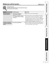
... Problem Fan does not operate when the switch is on Fan fails to plug it is loose or you see the connector dangling, the installer failed to circulate air or moves air slower than normal Possible Causes A fuse may not need to the unit. Troubleshooting Tips Save time...... Remove the filters and look up at the blower. Although it is loose or not plugged into its mating connector. See the Installation Instructions in . Safety Instructions Operating Instructions Care and Cleaning Troubleshooting Tips Consumer Support Before you may be blown or a circuit breaker tripped.
... Problem Fan does not operate when the switch is on Fan fails to plug it is loose or you see the connector dangling, the installer failed to circulate air or moves air slower than normal Possible Causes A fuse may not need to the unit. Troubleshooting Tips Save time...... Remove the filters and look up at the blower. Although it is loose or not plugged into its mating connector. See the Installation Instructions in . Safety Instructions Operating Instructions Care and Cleaning Troubleshooting Tips Consumer Support Before you may be blown or a circuit breaker tripped.
Use and Care Manual
Page 23
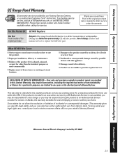
... to your state's Attorney General. Louisville, KY 40225 23 Safety Instructions Operating Instructions Care and Cleaning Troubleshooting Tips Consumer Support GE Range Hood Warranty. If the product is product repair as provided in materials or workmanship. Warrantor: General Electric Company. EXCLUSION... for a trip charge or you how to use the product. ■ Improper installation, delivery or maintenance. ■ Failure of God. ■ Incidental or consequential damage caused by a GE Authorized Servicer is needed to provide required service. Some states do not allow the ...
... to your state's Attorney General. Louisville, KY 40225 23 Safety Instructions Operating Instructions Care and Cleaning Troubleshooting Tips Consumer Support GE Range Hood Warranty. If the product is product repair as provided in materials or workmanship. Warrantor: General Electric Company. EXCLUSION... for a trip charge or you how to use the product. ■ Improper installation, delivery or maintenance. ■ Failure of God. ■ Incidental or consequential damage caused by a GE Authorized Servicer is needed to provide required service. Some states do not allow the ...


