
Installation Instructions
Page 3
...to be taken to align the exhaust with nuts #10 - 24 X 50 mm 4 LX-BZ0195WRE0 3 Top Cabinet Screw 5 X 60 mm 2 XBRSD50P60000 4 Power Cord Hanger 1 LX-MZB001MRE0 5 Tapping Screw 4 x 12 mm 3 XOTSD40P12000 6 Flat Washer 30 mm diameter 2 XWHSD50-16300 7 Grommet 1 LBSHC0040MRE0 8 Rear Cushion 1 PCUSUB059MRP0 9 ...-B002MRE0 Figure 4 Parts shown not to a standard 3-1/4" X 10" rectangular duct. Item Name Quantity Part Code 1 Wood Screw 5 X 30 mm 6 XTSSD50P35000 2 Toggle Bolt with the space between wall studs to -round adapter must be prepared at the time it is required, a ...
...to be taken to align the exhaust with nuts #10 - 24 X 50 mm 4 LX-BZ0195WRE0 3 Top Cabinet Screw 5 X 60 mm 2 XBRSD50P60000 4 Power Cord Hanger 1 LX-MZB001MRE0 5 Tapping Screw 4 x 12 mm 3 XOTSD40P12000 6 Flat Washer 30 mm diameter 2 XWHSD50-16300 7 Grommet 1 LBSHC0040MRE0 8 Rear Cushion 1 PCUSUB059MRP0 9 ...-B002MRE0 Figure 4 Parts shown not to a standard 3-1/4" X 10" rectangular duct. Item Name Quantity Part Code 1 Wood Screw 5 X 30 mm 6 XTSSD50P35000 2 Toggle Bolt with the space between wall studs to -round adapter must be prepared at the time it is required, a ...
Installation Instructions
Page 5
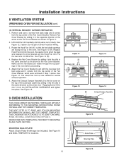
... Fan Unit 90˚ so that the fan blade openings are visible through the top openings in the oven before proceeding. 5. Use 1 Tapping Screw 4 X12 mm 5 from the INSTALLATION HARDWARE and tighten into Wire Box. Attach the Fan Cover Bracket to the fan cover on the Fan Cover Bracket. The Hood...
... Fan Unit 90˚ so that the fan blade openings are visible through the top openings in the oven before proceeding. 5. Use 1 Tapping Screw 4 X12 mm 5 from the INSTALLATION HARDWARE and tighten into Wire Box. Attach the Fan Cover Bracket to the fan cover on the Fan Cover Bracket. The Hood...