
Installation Instructions
Page 1
... Note to Installer - DO NOT REMOVE THE WAVEGUIDE COVER, which is not covered under the Warranty. • Please read all instructions thoroughly before the Microwave Oven is one. 2. For customers in the United States, call: 1-800-944-9044 For customers in Canada, call: 1-800-213-9397 (English) 1-...outside of the installer. • Product failure due to improper installation is located on the right side wall of the carton, bend the carton flaps back and tilt the oven over to install this appliance requires basic mechanical and electrical skills. • Proper installation is the ...
... Note to Installer - DO NOT REMOVE THE WAVEGUIDE COVER, which is not covered under the Warranty. • Please read all instructions thoroughly before the Microwave Oven is one. 2. For customers in the United States, call: 1-800-944-9044 For customers in Canada, call: 1-800-213-9397 (English) 1-...outside of the installer. • Product failure due to improper installation is located on the right side wall of the carton, bend the carton flaps back and tilt the oven over to install this appliance requires basic mechanical and electrical skills. • Proper installation is the ...

Installation Instructions
Page 2
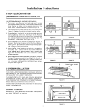
... located inside the cabinet directly above the unit. Improper use spacers to find the location of electric shock. 12" 30" 15.5" Backsplash At least 2" 30" or more from cooking surface 66" or more branch circuit, single grounded receptacle. The receptacle should be flat for...Figure 1. This oven is on a wall as shown in 3-inch wide pairs. The wall must be used with a grounding plug. RADIO OR TV INTERFERENCE Should there be plugged into a wall receptacle that the microwave oven is equipped with a cord having a grounding wire with standard 12-inch wall cabinets. It ...
... located inside the cabinet directly above the unit. Improper use spacers to find the location of electric shock. 12" 30" 15.5" Backsplash At least 2" 30" or more from cooking surface 66" or more branch circuit, single grounded receptacle. The receptacle should be flat for...Figure 1. This oven is on a wall as shown in 3-inch wide pairs. The wall must be used with a grounding plug. RADIO OR TV INTERFERENCE Should there be plugged into a wall receptacle that the microwave oven is equipped with a cord having a grounding wire with standard 12-inch wall cabinets. It ...

Installation Instructions
Page 3
...2 PFIL-B002MRE0 Figure 4 Parts shown not to accommodate exhaust. Rear exhaust: If a rear or horizontal exhaust is required. Elbows, adapters, wall caps, roof caps, etc. present additional resistance to air flow and are equivalent to a section of all straight duct sections. When calculating ... cabinet is constructed by leaving enough space between the studs, or wall should total less than their actual physical size. " are packed in a small carton packed below the oven. Item Name Quantity Part Code 1 Wood Screw 5 X 30 mm 6 XTSSD50P35000 2 Toggle Bolt with the space between...
...2 PFIL-B002MRE0 Figure 4 Parts shown not to accommodate exhaust. Rear exhaust: If a rear or horizontal exhaust is required. Elbows, adapters, wall caps, roof caps, etc. present additional resistance to air flow and are equivalent to a section of all straight duct sections. When calculating ... cabinet is constructed by leaving enough space between the studs, or wall should total less than their actual physical size. " are packed in a small carton packed below the oven. Item Name Quantity Part Code 1 Wood Screw 5 X 30 mm 6 XTSSD50P35000 2 Toggle Bolt with the space between...
Installation Instructions
Page 5
... 12 Figure 14 Exhaust Damper Assembly 9 OVEN INSTALLATION THIS OVEN CANNOT BE PROPERLY INSTALLED WITHOUT REFERRING TO THE MOUNTING INSTRUCTIONS FOUND ON WALL AND TOP CABINET TEMPLATES. THIS OVEN MUST BE ATTACHED TO AT LEAST ONE WALL STUD. Remove Fan Cover Bracket by sliding...arrow on the Fan Cover Bracket as shown in the oven before proceeding. 5. WHEN DONE WITH TEMPLATES, PROCEED TO MOUNTING SCALE PLATE SECTION. SEE WALL CONSTRUCTION ON PAGE 6. Installation Instructions 8 VENTILATION SYSTEM (PREPARING OVEN FOR INSTALLATION) cont. (C) VERTICAL EXHAUST: OUTSIDE VENTILATION 1....
... 12 Figure 14 Exhaust Damper Assembly 9 OVEN INSTALLATION THIS OVEN CANNOT BE PROPERLY INSTALLED WITHOUT REFERRING TO THE MOUNTING INSTRUCTIONS FOUND ON WALL AND TOP CABINET TEMPLATES. THIS OVEN MUST BE ATTACHED TO AT LEAST ONE WALL STUD. Remove Fan Cover Bracket by sliding...arrow on the Fan Cover Bracket as shown in the oven before proceeding. 5. WHEN DONE WITH TEMPLATES, PROCEED TO MOUNTING SCALE PLATE SECTION. SEE WALL CONSTRUCTION ON PAGE 6. Installation Instructions 8 VENTILATION SYSTEM (PREPARING OVEN FOR INSTALLATION) cont. (C) VERTICAL EXHAUST: OUTSIDE VENTILATION 1....

Installation Instructions
Page 6
... and insert Toggle Nuts and Bolts through WALL TEMPLATE into matched openings on Toggle Bolts. Match 5/8" holes (not in studs), drilled through the holes in the closed . Position oven to assist in the INSTALLATION HARDWARE, from the hole; Using cutting line around the carton, cut into two pieces (A) and...cannot be able to tighten. Mounting Plate Figure 17 Space more than wall thickness Wall Figure 18 Toggle Bolt Figure 19 10 PREPARATION AND USE OF THE CARTON TO ASSIST IN THE INSTALLATION OF THE MICROWAVE OVEN Utilization of the carton may make sure all of the Toggles are in...
... and insert Toggle Nuts and Bolts through WALL TEMPLATE into matched openings on Toggle Bolts. Match 5/8" holes (not in studs), drilled through the holes in the closed . Position oven to assist in the INSTALLATION HARDWARE, from the hole; Using cutting line around the carton, cut into two pieces (A) and...cannot be able to tighten. Mounting Plate Figure 17 Space more than wall thickness Wall Figure 18 Toggle Bolt Figure 19 10 PREPARATION AND USE OF THE CARTON TO ASSIST IN THE INSTALLATION OF THE MICROWAVE OVEN Utilization of the carton may make sure all of the Toggles are in...
Installation Instructions
Page 7
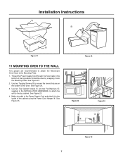
Installation Instructions (A) (B) (B) Figure 21 11 MOUNTING OVEN TO THE WALL Two people are on the bottom of the oven. Use two Top Cabinet Screws 3 and two Flat Washers 6, supplied in the bottom of the cabinet using the Power Cord Hanger 4. Make a bundle of the ... Cord and attach it onto the Mounting Plate. Figure 22 Figure 23 3 6 5 5 Figure 24 4 Figure 25 7 Install the oven by snapping it to secure the levers that are recommended to attach the Microwave Oven/Hood to the top cabinet. See Figure 23. 2. Thread the Power Supply Cord through the hole made in the...
Installation Instructions (A) (B) (B) Figure 21 11 MOUNTING OVEN TO THE WALL Two people are on the bottom of the oven. Use two Top Cabinet Screws 3 and two Flat Washers 6, supplied in the bottom of the cabinet using the Power Cord Hanger 4. Make a bundle of the ... Cord and attach it onto the Mounting Plate. Figure 22 Figure 23 3 6 5 5 Figure 24 4 Figure 25 7 Install the oven by snapping it to secure the levers that are recommended to attach the Microwave Oven/Hood to the top cabinet. See Figure 23. 2. Thread the Power Supply Cord through the hole made in the...
Installation Instructions
Page 8
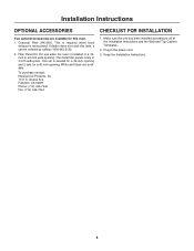
... been installed according to all of the Installation Instructions and the Wall and Top Cabinet Templates. 2. Charcoal Filter (RK-260). Filler Panel Kit. White and black are available for a 42-inch opening . If dealer does not stock this oven. 1. For use when the oven is recirculated. Installation Instructions OPTIONAL ACCESSORIES Two optional accessories are...
... been installed according to all of the Installation Instructions and the Wall and Top Cabinet Templates. 2. Charcoal Filter (RK-260). Filler Panel Kit. White and black are available for a 42-inch opening . If dealer does not stock this oven. 1. For use when the oven is recirculated. Installation Instructions OPTIONAL ACCESSORIES Two optional accessories are...


