Installation Manual
Page 1
GWX 70 Weather Radar Installation Manual 190-00829-01 October, 2012 Revision C
GWX 70 Weather Radar Installation Manual 190-00829-01 October, 2012 Revision C
Installation Manual
Page 5
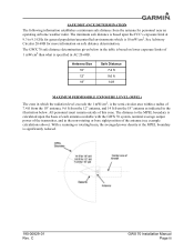
... the 1 mW/cm2, is specified in AC 20-68B. The minimum safe distance is based upon the basis of each antenna available with the GWX 70 system, nominal average output power of the transmitter, and in the non-rotating or bore sight position of this zone. SAFE DISTANCE DETERMINATION The following...illustration below. All personnel must remain outside of the antenna (see example calculations above). See Advisory Circular 20-68B for personnel near an operating airborne weather radar. With a scanning or rotating beam, the averaged power density at 9.3 to the MPEL boundary is 10 mW/cm2.
... the 1 mW/cm2, is specified in AC 20-68B. The minimum safe distance is based upon the basis of each antenna available with the GWX 70 system, nominal average output power of the transmitter, and in the non-rotating or bore sight position of this zone. SAFE DISTANCE DETERMINATION The following...illustration below. All personnel must remain outside of the antenna (see example calculations above). See Advisory Circular 20-68B for personnel near an operating airborne weather radar. With a scanning or rotating beam, the averaged power density at 9.3 to the MPEL boundary is 10 mW/cm2.
Installation Manual
Page 6
...be operated on the ground only by qualified personnel. When the antenna is being refueled or defueled. Airborne weather radar should be greater than that when high power radar transmitters are operated out of their protective cases, X-rays may result. 5. The distance from the glass ...envelope type pulser, oscillator, clipper, or rectifier tubes, as well as severe eye damage may be emitted. Personnel should not be reflected throughout the area. GWX 70...
...be operated on the ground only by qualified personnel. When the antenna is being refueled or defueled. Airborne weather radar should be greater than that when high power radar transmitters are operated out of their protective cases, X-rays may result. 5. The distance from the glass ...envelope type pulser, oscillator, clipper, or rectifier tubes, as well as severe eye damage may be emitted. Personnel should not be reflected throughout the area. GWX 70...
Installation Manual
Page 11
... do not possess the competencies and abilities set forth above. To the extent allowable by a Garmin-authorized installer. C GWX 70 Installation Manual Page 1-1 NOTE The ability of a weather radar system to your aircraft may compromise your safety and is not recommended. 1 GENERAL DESCRIPTION 1.1... installation specialists using standard aviation maintenance practices in elevation. This manual is highly dependent upon the quality of the Garmin GWX 70 Weather Radar into an aircraft. Refer to provide mechanical and electrical information for use in the planning and design of an...
... do not possess the competencies and abilities set forth above. To the extent allowable by a Garmin-authorized installer. C GWX 70 Installation Manual Page 1-1 NOTE The ability of a weather radar system to your aircraft may compromise your safety and is not recommended. 1 GENERAL DESCRIPTION 1.1... installation specialists using standard aviation maintenance practices in elevation. This manual is highly dependent upon the quality of the Garmin GWX 70 Weather Radar into an aircraft. Refer to provide mechanical and electrical information for use in the planning and design of an...
Installation Manual
Page 12
1.2 Equipment Description The Garmin GWX 70 Airborne Weather Radar is designed as an open architecture system that uses ARINC 429, ARINC 453, and Ethernet communications interfaces. Ground-based cellular telephones that are on the ground is off . C GWX 70 Installation Manual Page 1-2 190-00829-01 Rev...., can disrupt GPS performance. 1.3 Interface Summary The GWX 70 is a microprocessor-based Line Replaceable Unit (LRU) that outputs weather radar data to an external MFD. Due to FAA regulations 14 CFR 91.21. The GWX 70 communicates with onboard systems, the operation of ground-based...
1.2 Equipment Description The Garmin GWX 70 Airborne Weather Radar is designed as an open architecture system that uses ARINC 429, ARINC 453, and Ethernet communications interfaces. Ground-based cellular telephones that are on the ground is off . C GWX 70 Installation Manual Page 1-2 190-00829-01 Rev...., can disrupt GPS performance. 1.3 Interface Summary The GWX 70 is a microprocessor-based Line Replaceable Unit (LRU) that outputs weather radar data to an external MFD. Due to FAA regulations 14 CFR 91.21. The GWX 70 communicates with onboard systems, the operation of ground-based...
Installation Manual
Page 16
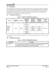
... if performed under 14 CFR part 43 or the applicable airworthiness requirements. 1.6.1 TSO/ETSO Compliance Table 1-5. GWX 70 TSO/ETSO Compliance Function Airborne Weather and Ground Mapping Pulsed Radars Performance Standard TSO-C63d Category Class B and C* Applicable LRU System SW Part Number All 006-B0756-0(_) ...installing this article are within a specific type or class of aircraft to utilize longer pulse durations than specified in an aircraft. Garmin was granted a deviation from RTCA/DO-173 as well as RTCA/DO-220 to determine that the aircraft installation conditions are ...
... if performed under 14 CFR part 43 or the applicable airworthiness requirements. 1.6.1 TSO/ETSO Compliance Table 1-5. GWX 70 TSO/ETSO Compliance Function Airborne Weather and Ground Mapping Pulsed Radars Performance Standard TSO-C63d Category Class B and C* Applicable LRU System SW Part Number All 006-B0756-0(_) ...installing this article are within a specific type or class of aircraft to utilize longer pulse durations than specified in an aircraft. Garmin was granted a deviation from RTCA/DO-173 as well as RTCA/DO-220 to determine that the aircraft installation conditions are ...

Installation Manual
Page 17
... found on www.garmin.com. 1.7.1 Operation In Weather Mode WARNING Begin transmitting only when it is safe to do so. This documentation can be used for field operating instructions. In Reversionary modes, the weather radar system continues to operate as long as at the center line. Touch the Display Mode Button. 4. C GWX 70 Installation Manual Page...
... found on www.garmin.com. 1.7.1 Operation In Weather Mode WARNING Begin transmitting only when it is safe to do so. This documentation can be used for field operating instructions. In Reversionary modes, the weather radar system continues to operate as long as at the center line. Touch the Display Mode Button. 4. C GWX 70 Installation Manual Page...
Installation Manual
Page 18
... the tilt angle. 3. Push the Joystick to disable the tilt adjustment function of the Joystick and display the Tilt Line on the Weather Radar Display. 3. GWX 70 Installation Manual Page 1-8 190-00829-01 Rev. When finished, press the Joystick again to show the Bearing Line on the... Weather Radar Display. 2. b) Touch the Horizontal Button. Touch the Altitude Comp Tilt Button. Press the Joystick again to activate the tilt adjustment function of the Joystick...
... the tilt angle. 3. Push the Joystick to disable the tilt adjustment function of the Joystick and display the Tilt Line on the Weather Radar Display. 3. GWX 70 Installation Manual Page 1-8 190-00829-01 Rev. When finished, press the Joystick again to show the Bearing Line on the... Weather Radar Display. 2. b) Touch the Horizontal Button. Touch the Altitude Comp Tilt Button. Press the Joystick again to activate the tilt adjustment function of the Joystick...

Installation Manual
Page 19
... green; C GWX 70 Installation Manual Page 1-9 The bearing reference is reset to change the center of the true intensity. To activate or deactivate the turbulence detection feature, touch the Turbulence Detection Button. 1.7.1.6 Adjusting Gain WARNING Changing the gain in weather mode causes precipitation intensity to show the Bearing Line on the Weather Radar display. 3. From...
... green; C GWX 70 Installation Manual Page 1-9 The bearing reference is reset to change the center of the true intensity. To activate or deactivate the turbulence detection feature, touch the Turbulence Detection Button. 1.7.1.6 Adjusting Gain WARNING Changing the gain in weather mode causes precipitation intensity to show the Bearing Line on the Weather Radar display. 3. From...

Installation Manual
Page 20
...Button. From Home, touch Weather > Weather Selection > WX RADAR > WX RADAR Settings. 2. Use the Joystick to place the radar in Ground Map Mode 1. WATCH is disabled when button annunciator is green; From Home, touch Weather > Weather Selection > WX RADAR > WX RADAR Settings. 2. Touch the ...gray. 1.7.1.11 Enabling/Displaying Weather Alert 1. ground clutter suppression is disabled when annunciator is gray. 1.7.1.12 Enabling/Disabling Ground Clutter Suppression 1. Press the Joystick to disable the tilt adjustment function of the Joystick. GWX 70 Installation Manual Page 1-10 ...
...Button. From Home, touch Weather > Weather Selection > WX RADAR > WX RADAR Settings. 2. Use the Joystick to place the radar in Ground Map Mode 1. WATCH is disabled when button annunciator is green; From Home, touch Weather > Weather Selection > WX RADAR > WX RADAR Settings. 2. Touch the ...gray. 1.7.1.11 Enabling/Displaying Weather Alert 1. ground clutter suppression is disabled when annunciator is gray. 1.7.1.12 Enabling/Disabling Ground Clutter Suppression 1. Press the Joystick to disable the tilt adjustment function of the Joystick. GWX 70 Installation Manual Page 1-10 ...
Installation Manual
Page 23
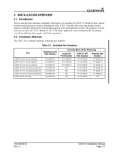
... AC 43.13-1B and AC 43.13-2B, where applicable, may be found useful for installing the GWX 70 Weather Radar, related hardware and optional accessories. C GWX 70 Installation Manual Page 2-1 Installation of the Following Install Kit Part Number 011-01769-00 011-01769-00 011-01769... Available Part Numbers Item Shipping Level Part Number GWX 70 w/10" Ant, w/Install Kit GWX 70 w/12" Ant, w/Install Kit GWX 70 w/18" Ant, w/Install Kit GWX 70 w/10" Ant, without Install Kit GWX 70 w/12" Ant, without Install Kit GWX 70 w/18" Ant, without Install Kit GWX 70 R/T (unit only) 010-00676-00 010-...
... AC 43.13-1B and AC 43.13-2B, where applicable, may be found useful for installing the GWX 70 Weather Radar, related hardware and optional accessories. C GWX 70 Installation Manual Page 2-1 Installation of the Following Install Kit Part Number 011-01769-00 011-01769-00 011-01769... Available Part Numbers Item Shipping Level Part Number GWX 70 w/10" Ant, w/Install Kit GWX 70 w/12" Ant, w/Install Kit GWX 70 w/18" Ant, w/Install Kit GWX 70 w/10" Ant, without Install Kit GWX 70 w/12" Ant, without Install Kit GWX 70 w/18" Ant, without Install Kit GWX 70 R/T (unit only) 010-00676-00 010-...
Installation Manual
Page 30
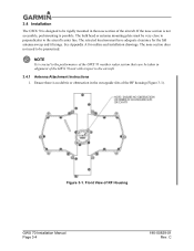
...1. See Appendix A for the full antenna sweep and tilt range. Ensure there is no debris or obstruction in the waveguide slits of RF Housing GWX 70 Installation Manual Page 3-4 190-00829-01 Rev. Figure 3-1. NOTE It is possible. C The bulk head or antenna mounting plate must have adequate ...of the aircraft. If the nose section is not accessible, pod mounting is crucial to the performance of the GWX 70 weather radar system that care be taken in the nose section of the GWX 70 unit with respect to be pressurized. The nose section does not need to the aircraft center line.
...1. See Appendix A for the full antenna sweep and tilt range. Ensure there is no debris or obstruction in the waveguide slits of RF Housing GWX 70 Installation Manual Page 3-4 190-00829-01 Rev. Figure 3-1. NOTE It is possible. C The bulk head or antenna mounting plate must have adequate ...of the aircraft. If the nose section is not accessible, pod mounting is crucial to the performance of the GWX 70 weather radar system that care be taken in the nose section of the GWX 70 unit with respect to be pressurized. The nose section does not need to the aircraft center line.

Installation Manual
Page 38
... aircraft-specific GX000 Software Loader Card. View the Weather Radar page on the MFD and ensure that are completed. GWX 70 Installation Manual Page 3-12 190-00829-01 Rev. For the installer's convenience, a label has been applied adjacent to the G1000 Line Maintenance Manual and Configuration Manual, Garmin part number 190-00303-04. Configuration data...
... aircraft-specific GX000 Software Loader Card. View the Weather Radar page on the MFD and ensure that are completed. GWX 70 Installation Manual Page 3-12 190-00829-01 Rev. For the installer's convenience, a label has been applied adjacent to the G1000 Line Maintenance Manual and Configuration Manual, Garmin part number 190-00303-04. Configuration data...

