Use and Care Manual
Page 2
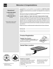
...consider us for future reference. Common sense and caution must be filled in United States Cooktop Serial Plate Location Versión en español Si desea obtener una copia en ...Products. O. Serial Plate Location © 2006 Electrolux Canada Corp. Box 212378 Augusta, GA 30917 PLEASE CAREFULLY READ AND SAVE THESE INSTRUCTIONS This Use & Care Manual contains general ... Date: Product Registration Register Your Product The PRODUCT REGISTRATION CARD should be practiced when installing, operating and maintaining any appliance. Your product may not look exactly like those shown...
...consider us for future reference. Common sense and caution must be filled in United States Cooktop Serial Plate Location Versión en español Si desea obtener una copia en ...Products. O. Serial Plate Location © 2006 Electrolux Canada Corp. Box 212378 Augusta, GA 30917 PLEASE CAREFULLY READ AND SAVE THESE INSTRUCTIONS This Use & Care Manual contains general ... Date: Product Registration Register Your Product The PRODUCT REGISTRATION CARD should be practiced when installing, operating and maintaining any appliance. Your product may not look exactly like those shown...

Use and Care Manual
Page 3
...; Immediately call the fire department. - Never allow children to play around the cooktop. Among these instructions for this manual is properly installed and grounded by a qualified installer, servicer or the gas supplier. • Remove all instructions given. Stepping or leaning on the cooktop. Do not allow children to climb or play with the National Fuel...
...; Immediately call the fire department. - Never allow children to play around the cooktop. Among these instructions for this manual is properly installed and grounded by a qualified installer, servicer or the gas supplier. • Remove all instructions given. Stepping or leaning on the cooktop. Do not allow children to climb or play with the National Fuel...

Use and Care Manual
Page 5
..., or remove grounding prong from this cooktop and is located in order for this cooktop for conversion to satisfactorily meet the application needs must be properly grounded. conversion is not installed by a qualified electrician. This appliance is designed to allow for complete installation and grounding instructions. Gas) This natural gas range is equipped with 3-prong grounding...
..., or remove grounding prong from this cooktop and is located in order for this cooktop for conversion to satisfactorily meet the application needs must be properly grounded. conversion is not installed by a qualified electrician. This appliance is designed to allow for complete installation and grounding instructions. Gas) This natural gas range is equipped with 3-prong grounding...
Use and Care Manual
Page 6
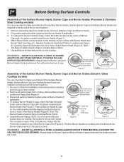
... of the Surface Burner Heads, Surface Burner Caps and Surface Burner Grates are installed correctly and at the correct locations. 1. NOTE: Do not force End Burner Figure 5 Figure 3 Grates down on the cooktop. Discard all the Burner Grate legs lie on each Burner Head (Figure 3)....DO NOT ALLOW SPILLS, FOOD, CLEANING AGENTS OR ANY OTHER MATERIAL TO ENTER THE GAS ORIFICE HOLDER OPENING. Remove all Burner Caps and Burner Heads. 2. Note: The Burner Heads should sit flat on Cooktop Burner Skirts. 5. Before Setting Surface Controls Assembly of the Surface Burner Heads, Burner...
... of the Surface Burner Heads, Surface Burner Caps and Surface Burner Grates are installed correctly and at the correct locations. 1. NOTE: Do not force End Burner Figure 5 Figure 3 Grates down on the cooktop. Discard all the Burner Grate legs lie on each Burner Head (Figure 3)....DO NOT ALLOW SPILLS, FOOD, CLEANING AGENTS OR ANY OTHER MATERIAL TO ENTER THE GAS ORIFICE HOLDER OPENING. Remove all Burner Caps and Burner Heads. 2. Note: The Burner Heads should sit flat on Cooktop Burner Skirts. 5. Before Setting Surface Controls Assembly of the Surface Burner Heads, Burner...
Installation Instructions
Page 1
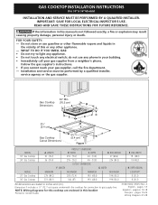
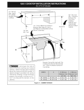
... in inches and (cm). pages 19-26 Wiring Diagram 27-28 Installation and service must be performed by a qualified installer, service agency or the gas supplier. 30" Min. * Gas Cooktop (76.2 cm) Dimensions B A C E D 2½" H (6.4 cm) G 2½" F Gas Cooktop (6.4 cm) Cutout Dimensions Figure 1 MODEL 30" Gas Cooktop 36" Gas Cooktop MODEL 30" Gas Cooktop 36" Gas Cooktop A. BOX WIDTH 19 (48.3) 19 (48.3) H. pages 1-9 Español - do...
... in inches and (cm). pages 19-26 Wiring Diagram 27-28 Installation and service must be performed by a qualified installer, service agency or the gas supplier. 30" Min. * Gas Cooktop (76.2 cm) Dimensions B A C E D 2½" H (6.4 cm) G 2½" F Gas Cooktop (6.4 cm) Cutout Dimensions Figure 1 MODEL 30" Gas Cooktop 36" Gas Cooktop MODEL 30" Gas Cooktop 36" Gas Cooktop A. BOX WIDTH 19 (48.3) 19 (48.3) H. pages 1-9 Español - do...

Installation Instructions
Page 2
.... The electrical power to the Consumer Keep these instructions with any other appliance. IMPORTANT SAFETY INSTRUCTIONS Installation of interest to reach over the surface burners, cabinet storage space above the burners should follow. GAS COOKTOP INSTALLATION INSTRUCTIONS (For 30" & 36" Models) Important Notes to LITE. Read all governing codes and ordinances. 4. Remove all packing material...
.... The electrical power to the Consumer Keep these instructions with any other appliance. IMPORTANT SAFETY INSTRUCTIONS Installation of interest to reach over the surface burners, cabinet storage space above the burners should follow. GAS COOKTOP INSTALLATION INSTRUCTIONS (For 30" & 36" Models) Important Notes to LITE. Read all governing codes and ordinances. 4. Remove all packing material...
Installation Instructions
Page 3
...Left Side 5" (12.7 cm) 5" (12.7 cm) C. CABINET DESIGN 3 MODEL 30" Cooktop 36" Cooktop A 30" (76.2 cm) 36" (91.4 cm) B. Depth For Cabinet A Installed Above Cooktop. 18" Min. (45.7 cm) 1½" (3.8 cm)Minimum Distance Between Rear Edge of ...Cooktop Since Burner Box Extends 35/32" (8.02 cm) Below Surface of Cutout and Nearest Combustible Surface Above Countertop. If cabinet storage is provided, risk can be avoided. Clearance 30" (76.2 cm) Min. Minimum Clearance from Right Side 5" (12.7 cm) 5" (12.7 cm) Figure 2 - GAS COOKTOP INSTALLATION INSTRUCTIONS (For 30" & 36...
...Left Side 5" (12.7 cm) 5" (12.7 cm) C. CABINET DESIGN 3 MODEL 30" Cooktop 36" Cooktop A 30" (76.2 cm) 36" (91.4 cm) B. Depth For Cabinet A Installed Above Cooktop. 18" Min. (45.7 cm) 1½" (3.8 cm)Minimum Distance Between Rear Edge of ...Cooktop Since Burner Box Extends 35/32" (8.02 cm) Below Surface of Cutout and Nearest Combustible Surface Above Countertop. If cabinet storage is provided, risk can be avoided. Clearance 30" (76.2 cm) Min. Minimum Clearance from Right Side 5" (12.7 cm) 5" (12.7 cm) Figure 2 - GAS COOKTOP INSTALLATION INSTRUCTIONS (For 30" & 36...

Installation Instructions
Page 4
... electric oven models. from adjoining cabinets. Must be maintained. OVEN SIZE 30" (76.2 cm) 27" (68.6 cm) CUTOUT DIMENSIONS (inches) E Min. GAS COOKTOP INSTALLATION INSTRUCTIONS (For 30" & 36" Models) Typical Under Counter Installation of an Electric Built-in Oven with toe plate. Junction box must be used to secure the built-in oven to the...
... electric oven models. from adjoining cabinets. Must be maintained. OVEN SIZE 30" (76.2 cm) 27" (68.6 cm) CUTOUT DIMENSIONS (inches) E Min. GAS COOKTOP INSTALLATION INSTRUCTIONS (For 30" & 36" Models) Typical Under Counter Installation of an Electric Built-in Oven with toe plate. Junction box must be used to secure the built-in oven to the...
Installation Instructions
Page 5
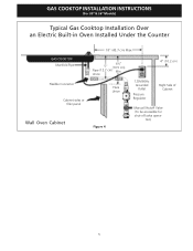
tion) 5 Union Flare Union Figure 4 4" (10.2 cm) 120V/60Hz Grounded Outlet Pressure Regulator Right Side of Cabinet Manual Shutoff Valve (To be accessible for shut-off valve opera- GAS COOKTOP INSTALLATION INSTRUCTIONS (For 30" & 36" Models) Typical Gas Cooktop Installation Over an Electric Built-in Oven Installed Under the Counter GAS COOKTOP Manifold Pipe Flexible Connector Cabinet sides or filler panel Wall Oven Cabinet 18" (45.7 cm) Max. 6½" 5" (16.5 cm) Flare (12.7 cm) Min.
tion) 5 Union Flare Union Figure 4 4" (10.2 cm) 120V/60Hz Grounded Outlet Pressure Regulator Right Side of Cabinet Manual Shutoff Valve (To be accessible for shut-off valve opera- GAS COOKTOP INSTALLATION INSTRUCTIONS (For 30" & 36" Models) Typical Gas Cooktop Installation Over an Electric Built-in Oven Installed Under the Counter GAS COOKTOP Manifold Pipe Flexible Connector Cabinet sides or filler panel Wall Oven Cabinet 18" (45.7 cm) Max. 6½" 5" (16.5 cm) Flare (12.7 cm) Min.
Installation Instructions
Page 6
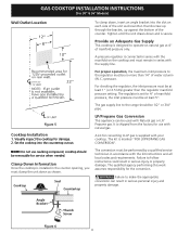
... service when needed. GAS COOKTOP INSTALLATION INSTRUCTIONS (For 30" & 36" Models) Wall Outlet Location To clamp down as shown.Run thumb screw up through the bracket, up against the bottom of the counter. For proper operation, the maximum inlet pressure to the regulator must remain in series with your cooktop. The gas supply line to the...
... service when needed. GAS COOKTOP INSTALLATION INSTRUCTIONS (For 30" & 36" Models) Wall Outlet Location To clamp down as shown.Run thumb screw up through the bracket, up against the bottom of the counter. For proper operation, the maximum inlet pressure to the regulator must remain in series with your cooktop. The gas supply line to the...
Installation Instructions
Page 7
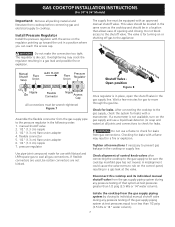
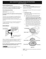
GAS COOKTOP INSTALLATION INSTRUCTIONS (For 30" & 36" Models) Important: Remove all packing material and literature from gas connections. manual shutoff valve 2. 1/2" (1.3 cm) nipple 3. 1/2" (1.3 cm) flare union adapter 4. pressure regulator Use pipe-joint compound made for use with Natural and LP/Propane gas to seal all joints and connections ...to check for leaks with an approved manual shutoff valve. This valve should be located in the same room as the cooktop and should be in the following order: 1....
GAS COOKTOP INSTALLATION INSTRUCTIONS (For 30" & 36" Models) Important: Remove all packing material and literature from gas connections. manual shutoff valve 2. 1/2" (1.3 cm) nipple 3. 1/2" (1.3 cm) flare union adapter 4. pressure regulator Use pipe-joint compound made for use with Natural and LP/Propane gas to seal all joints and connections ...to check for leaks with an approved manual shutoff valve. This valve should be located in the same room as the cooktop and should be in the following order: 1....
Installation Instructions
Page 8
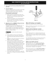
GAS COOKTOP INSTALLATION INSTRUCTIONS (For 30" & 36" Models) Electrical Requirements 120 volt, 60 Hertz, properly grounded branch circuit protected by a properly grounded 3prong wall receptacle. Install Burner Caps This cooktop is properly grounded. Unpack your cooktop. Grounding type wall receptacle Do not, under any circumstances, cut or remove the third (ground) prong from wall receptacle before servicing cooktop. Figure...
GAS COOKTOP INSTALLATION INSTRUCTIONS (For 30" & 36" Models) Electrical Requirements 120 volt, 60 Hertz, properly grounded branch circuit protected by a properly grounded 3prong wall receptacle. Install Burner Caps This cooktop is properly grounded. Unpack your cooktop. Grounding type wall receptacle Do not, under any circumstances, cut or remove the third (ground) prong from wall receptacle before servicing cooktop. Figure...
Installation Instructions
Page 9
...adjust to the warranty in and turn clockwise. Push in your Use and Care Guide. Flame size can quickly turn the knob of the cooktop. Use the marks as a guide and adjust the flame as possible without extinguishing the flame. D. Flame should be sure to include ..., the type of Surface Burner Valves (see Figure 11) Push in your Use and Care Guide for or making inquires about your cooktop. GAS COOKTOP INSTALLATION INSTRUCTIONS (For 30" & 36" Models) 2. After the burner lights, turn each burner has been set them at a particular mark. The controls do not have...
...adjust to the warranty in and turn clockwise. Push in your Use and Care Guide. Flame size can quickly turn the knob of the cooktop. Use the marks as a guide and adjust the flame as possible without extinguishing the flame. D. Flame should be sure to include ..., the type of Surface Burner Valves (see Figure 11) Push in your Use and Care Guide for or making inquires about your cooktop. GAS COOKTOP INSTALLATION INSTRUCTIONS (For 30" & 36" Models) 2. After the burner lights, turn each burner has been set them at a particular mark. The controls do not have...


