FE 8845A & 8846A Users Manual
Page 2
...date of any other provision. This warranty extends only to the original buyer or end-user customer of a Fluke authorized reseller, and does not apply to fuses, disposable batteries, or to any provision of this Warranty is returned to invoice Buyer for the repair and return...by neglect, misuse, contamination, alteration, accident, or abnormal condition of the difficulty, postage and insurance prepaid (FOB Destination). Fluke reserves the right to a Fluke authorized service center within the warranty period. Since some countries or states do not allow limitation of the term of an ...
...date of any other provision. This warranty extends only to the original buyer or end-user customer of a Fluke authorized reseller, and does not apply to fuses, disposable batteries, or to any provision of this Warranty is returned to invoice Buyer for the repair and return...by neglect, misuse, contamination, alteration, accident, or abnormal condition of the difficulty, postage and insurance prepaid (FOB Destination). Fluke reserves the right to a Fluke authorized service center within the warranty period. Since some countries or states do not allow limitation of the term of an ...
FE 8845A & 8846A Users Manual
Page 4
8845A/8846A Users Manual 2 3 Diode Test ...1-20 Measurement Rates 1-20 Preparing the Meter for Operation 2-1 Introduction...2-3 Unpacking and Inspecting the Meter 2-3 Contacting Fluke 2-3 Storing and Shipping the Meter 2-3 Power Considerations 2-3 Selecting the Line Voltage 2-4 Replacing the Fuses 2-4 Connecting to Line Power 2-7 Turning Power-On 2-8 Adjusting the Bail 2-8 Installing the Meter in an Equipment Rack...
8845A/8846A Users Manual 2 3 Diode Test ...1-20 Measurement Rates 1-20 Preparing the Meter for Operation 2-1 Introduction...2-3 Unpacking and Inspecting the Meter 2-3 Contacting Fluke 2-3 Storing and Shipping the Meter 2-3 Power Considerations 2-3 Selecting the Line Voltage 2-4 Replacing the Fuses 2-4 Connecting to Line Power 2-7 Turning Power-On 2-8 Adjusting the Bail 2-8 Installing the Meter in an Equipment Rack...

FE 8845A & 8846A Users Manual
Page 7
Accessories...1-7 2-1. Safety and Electrical Symbols 1-6 1-3. Line Power Cord Types Available from Fluke 2-7 3-1. Display Elements 3-5 3-3. Non-volatile Memory Space 1-7 1-3. Front-Panel Controls and Connectors 3-3 3-2. List of Tables Table Title Page 1-1. Line Voltage to Signal List C-1 v Rear-Panel Conncetors 3-6 C-1. Volatile Memory Space 1-6 1-4. Safety Information 1-5 1-2. RS-232 Pin to Fuse Rating 2-5 2-2.
Accessories...1-7 2-1. Safety and Electrical Symbols 1-6 1-3. Line Power Cord Types Available from Fluke 2-7 3-1. Display Elements 3-5 3-3. Non-volatile Memory Space 1-7 1-3. Front-Panel Controls and Connectors 3-3 3-2. List of Tables Table Title Page 1-1. Line Voltage to Signal List C-1 v Rear-Panel Conncetors 3-6 C-1. Volatile Memory Space 1-6 1-4. Safety Information 1-5 1-2. RS-232 Pin to Fuse Rating 2-5 2-2.

FE 8845A & 8846A Users Manual
Page 9
Input Connections for Current Measurements Above 120 mA 4-10 4-6. Diode Testing Connections 4-15 4-9. Replacing the Current Input Fuses 2-6 2-3. Bail Adjustment and Removal 2-8 3-1. Input Connections for 4-Wire Resistance Measurements 4-8 4-3. TRIG I/O Pin-out Description 4-17 vii Input Connections for 4-wire ohms ...2-1. Input Connections for Voltage, Resistance, and Frequency Measurements .......... 4-4 4-2. Temperature Measurements 4-13 4-8. Histogram Display 3-14 4-1. Line Power Cords Types Available from Fluke 2-7 2-4. Replacing the Line Fuse 2-5 2-2.
Input Connections for Current Measurements Above 120 mA 4-10 4-6. Diode Testing Connections 4-15 4-9. Replacing the Current Input Fuses 2-6 2-3. Bail Adjustment and Removal 2-8 3-1. Input Connections for 4-Wire Resistance Measurements 4-8 4-3. TRIG I/O Pin-out Description 4-17 vii Input Connections for 4-wire ohms ...2-1. Input Connections for Voltage, Resistance, and Frequency Measurements .......... 4-4 4-2. Temperature Measurements 4-13 4-8. Histogram Display 3-14 4-1. Line Power Cords Types Available from Fluke 2-7 2-4. Replacing the Line Fuse 2-5 2-2.

FE 8845A & 8846A Users Manual
Page 15
... doubt, have the Meter serviced. • Whenever it is exposed. These voltages pose a shock hazard. • Use only the replacement fuse(s) specified by qualified service personnel. • Do not apply more than the rated voltage, as specified in wet environments. • Inspect ...circuit power and discharge all high-voltage capacitors before testing resistance, continuity, diodes, or capacitance. • Before measuring current, check the Meter's fuses and turn OFF power to the circuit. • When servicing the Meter, use only specified replacement parts. 1-5 Do not use . 1 ...
... doubt, have the Meter serviced. • Whenever it is exposed. These voltages pose a shock hazard. • Use only the replacement fuse(s) specified by qualified service personnel. • Do not apply more than the rated voltage, as specified in wet environments. • Inspect ...circuit power and discharge all high-voltage capacitors before testing resistance, continuity, diodes, or capacitance. • Before measuring current, check the Meter's fuses and turn OFF power to the circuit. • When servicing the Meter, use only specified replacement parts. 1-5 Do not use . 1 ...

FE 8845A & 8846A Users Manual
Page 16
...Current) Symbol O Description Display ON / OFF J Earth ground E G I Y Capacitance Diode Fuse Digital signal R Continuity test or continuity beeper U Maintenance or Service tone Y Potentially hazardous voltage CAT II... IEC 61010 Overvoltage (installation or measurement) Category 2. Contact Fluke or a qualified recycler for disposal Instrument Security Procedures This section describes ...soft key. 1-6 Important information. In-guard Measurement data and configuration information. 8845A/8846A Users Manual Symbols Table 1-2 is a list of safety and electrical symbols...
...Current) Symbol O Description Display ON / OFF J Earth ground E G I Y Capacitance Diode Fuse Digital signal R Continuity test or continuity beeper U Maintenance or Service tone Y Potentially hazardous voltage CAT II... IEC 61010 Overvoltage (installation or measurement) Category 2. Contact Fluke or a qualified recycler for disposal Instrument Security Procedures This section describes ...soft key. 1-6 Important information. In-guard Measurement data and configuration information. 8845A/8846A Users Manual Symbols Table 1-2 is a list of safety and electrical symbols...
FE 8845A & 8846A Users Manual
Page 18
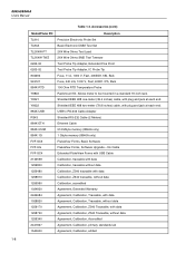
...Calibration, Traceable, without data Agreement, Calibration, Z540 Traceable, with plug and jack at each end. Accessories (cont) Model/Fluke PN Description TL910 TL80A TL2X4W-PT TL2X4W-TWZ 6262-02 6263-02 803293 943121 884X-RTD Y8846 Y8021 Y8022 884X-USB ... Fuse, 440 mA, 1000 V, Fast, 406X1.375, Buik 100 Ohm RTD Temperature Probe Rackmount Kit. Shielded IEEE 488 two-meter (78.8 inches) cable, with data Agreement, Calibration, Z540 Traceable, without data Agreement, Calibration, Accredited Agreement, Calibration, primary standards lab Agreement, Calibration, artifact 1-8 8845A/...
...Calibration, Traceable, without data Agreement, Calibration, Z540 Traceable, with plug and jack at each end. Accessories (cont) Model/Fluke PN Description TL910 TL80A TL2X4W-PT TL2X4W-TWZ 6262-02 6263-02 803293 943121 884X-RTD Y8846 Y8021 Y8022 884X-USB ... Fuse, 440 mA, 1000 V, Fast, 406X1.375, Buik 100 Ohm RTD Temperature Probe Rackmount Kit. Shielded IEEE 488 two-meter (78.8 inches) cable, with data Agreement, Calibration, Z540 Traceable, without data Agreement, Calibration, Accredited Agreement, Calibration, primary standards lab Agreement, Calibration, artifact 1-8 8845A/...

FE 8845A & 8846A Users Manual
Page 25
...; 1 Ω 1 Ω 0.01 Ω 0.01 Ω 0.01 Ω 1 Introduction and Specifications Electrical Specifications DC Current Input Protection Tool-accessible 11 A/1000 V and 440 mA/1000 V fuses.
...; 1 Ω 1 Ω 0.01 Ω 0.01 Ω 0.01 Ω 1 Introduction and Specifications Electrical Specifications DC Current Input Protection Tool-accessible 11 A/1000 V and 440 mA/1000 V fuses.

FE 8845A & 8846A Users Manual
Page 26
For inputs from 1% to 10 kHz Maximum Crest Factor 5:1 at full scale Additional Crest Factor Errors ( Measurement Method ac-coupled true-rms, dc-coupled to the fuse and shunt (no blocking capacitor) AC Filter Bandwidth Slow 3 Hz to 10 kHz Medium 20 Hz to 10 kHz Fast 200 Hz to 5 % of range, add an additional error of 0.1 % of range. 8845A/8846A Users Manual AC Current The following ac current specifications are for sinusoidal signals with amplitudes greater than 5 % of range. Input Protection Tool accessible 11 A/1000 V and 440 mA/1000 V fuses.
For inputs from 1% to 10 kHz Maximum Crest Factor 5:1 at full scale Additional Crest Factor Errors ( Measurement Method ac-coupled true-rms, dc-coupled to the fuse and shunt (no blocking capacitor) AC Filter Bandwidth Slow 3 Hz to 10 kHz Medium 20 Hz to 10 kHz Fast 200 Hz to 5 % of range, add an additional error of 0.1 % of range. 8845A/8846A Users Manual AC Current The following ac current specifications are for sinusoidal signals with amplitudes greater than 5 % of range. Input Protection Tool accessible 11 A/1000 V and 440 mA/1000 V fuses.

FE 8845A & 8846A Users Manual
Page 31
Chapter 2 Preparing the Meter for Operation Title Page Introduction...2-3 Unpacking and Inspecting the Meter 2-3 Contacting Fluke 2-3 Storing and Shipping the Meter 2-3 Power Considerations 2-3 Selecting the Line Voltage 2-4 Replacing the Fuses 2-4 Line-Power Fuse 2-4 Current-Input Fuses 2-5 Connecting to Line Power 2-7 Turning Power-On 2-8 Adjusting the Bail 2-8 Installing the Meter in an Equipment Rack 2-8 Cleaning the Meter 2-9 2-1
Chapter 2 Preparing the Meter for Operation Title Page Introduction...2-3 Unpacking and Inspecting the Meter 2-3 Contacting Fluke 2-3 Storing and Shipping the Meter 2-3 Power Considerations 2-3 Selecting the Line Voltage 2-4 Replacing the Fuses 2-4 Line-Power Fuse 2-4 Current-Input Fuses 2-5 Connecting to Line Power 2-7 Turning Power-On 2-8 Adjusting the Bail 2-8 Installing the Meter in an Equipment Rack 2-8 Cleaning the Meter 2-9 2-1
FE 8845A & 8846A Users Manual
Page 34
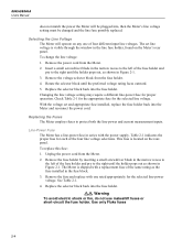
... operation. The Meter is shipped with a replacement fuse of the same rating as shown in Figure 2-1. Use only Fluke fuses 2-4 Changing the line voltage setting may require a different line-power fuse for each of four different input line voltages. Unplug the power cord from the Meter. 2. 8845A/8846A Users Manual does not match the power...
... operation. The Meter is shipped with a replacement fuse of the same rating as shown in Figure 2-1. Use only Fluke fuses 2-4 Changing the line voltage setting may require a different line-power fuse for each of four different input line voltages. Unplug the power cord from the Meter. 2. 8845A/8846A Users Manual does not match the power...

FE 8845A & 8846A Users Manual
Page 35
...the other end of the test lead into the VΩGER connector. 2. If the fuse is blown, the Meter will read overload. 4. Press N. 3. Remove the probe from Fluke. If the fuse is good, the Meter will read less than 200 Ω. W Warning For protection ...). • The 10 A input is protected by a fuse (F1) rated at 11 A, 1000 V (fast blow), 10,000 A minimum breaking capacity (Fluke Part No. 803293). 2 Preparing the Meter for a blown Current Input Fuse: 1. Line Voltage to Fuse Rating Line Voltage Selection Fuse Rating Fluke Part No. 100 0.25 A, 250 V (slow blow)...
...the other end of the test lead into the VΩGER connector. 2. If the fuse is blown, the Meter will read overload. 4. Press N. 3. Remove the probe from Fluke. If the fuse is good, the Meter will read less than 200 Ω. W Warning For protection ...). • The 10 A input is protected by a fuse (F1) rated at 11 A, 1000 V (fast blow), 10,000 A minimum breaking capacity (Fluke Part No. 803293). 2 Preparing the Meter for a blown Current Input Fuse: 1. Line Voltage to Fuse Rating Line Voltage Selection Fuse Rating Fluke Part No. 100 0.25 A, 250 V (slow blow)...

FE 8845A & 8846A Users Manual
Page 36
... the Meter, and remove all test leads. 2. If the fuse is good, the Meter will read less than 1 Ω. Fuses F1 F2 Bottom front left corner Figure 2-2. Remove the defective fuse, and replace with the holes in Figure 2-2. 4. 8845A/8846A Users Manual If the fuse is blown, the Meter will read overload. Unscrew the retaining...
... the Meter, and remove all test leads. 2. If the fuse is good, the Meter will read less than 1 Ω. Fuses F1 F2 Bottom front left corner Figure 2-2. Remove the defective fuse, and replace with the holes in Figure 2-2. 4. 8845A/8846A Users Manual If the fuse is blown, the Meter will read overload. Unscrew the retaining...
FE 8845A & 8846A Users Manual
Page 37
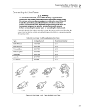
... correct fuse for Operation Connecting to Line Power Connecting to Line Power XWWarning To avoid shock hazard, connect the factory supplied threeconductor line power cord to a properly grounded power outlet. First verify that the line voltage selection is installed. Line Power Cord Types Available from Fluke alh3... earth ground before connecting the power cord or operating the instrument. Line Power Cords Types Available from Fluke Voltage/Current 120V/15A 240V/15A 220V/16A 240V/13A 220V/10A 240V/10A 240V/5A Fluke Model Number LC-1 LC-2 LC-3 LC-4 LC-5 LC-6 LC-7 LC-1 LC-2 LC-3 LC...
... correct fuse for Operation Connecting to Line Power Connecting to Line Power XWWarning To avoid shock hazard, connect the factory supplied threeconductor line power cord to a properly grounded power outlet. First verify that the line voltage selection is installed. Line Power Cord Types Available from Fluke alh3... earth ground before connecting the power cord or operating the instrument. Line Power Cords Types Available from Fluke Voltage/Current 120V/15A 240V/15A 220V/16A 240V/13A 220V/10A 240V/10A 240V/5A Fluke Model Number LC-1 LC-2 LC-3 LC-4 LC-5 LC-6 LC-7 LC-1 LC-2 LC-3 LC...

FE 8845A & 8846A Users Manual
Page 43
... input. Front-Panel Controls and Connectors 1 2 3 4 INPUT V 2W/4W HI SENSE 4W HI 1000 V CAT I 600V CAT II 300 V LO LO 1V FUSED 100 mA 10 A REAR FRONT 8846A 6-1/2 DIGIT PRECISION MULTIMETER BACK F1 F2 F3 F4 F5 RANGE DC V AC V DC I FREQ PERIOD AC I TEMP TRIG INSTR... SETUP ZERO ANALYZE MEAS SETUP MEMORY 16 15 14 13 12 11 10 8 6 8845A Only FREQ PERIOD 97 5 Item A caw04.eps Description Input HI and LO connectors. Input connectors for Volts, 2-wire Ohms, Hz, Period, Temperature, and Capacitance...
... input. Front-Panel Controls and Connectors 1 2 3 4 INPUT V 2W/4W HI SENSE 4W HI 1000 V CAT I 600V CAT II 300 V LO LO 1V FUSED 100 mA 10 A REAR FRONT 8846A 6-1/2 DIGIT PRECISION MULTIMETER BACK F1 F2 F3 F4 F5 RANGE DC V AC V DC I FREQ PERIOD AC I TEMP TRIG INSTR... SETUP ZERO ANALYZE MEAS SETUP MEMORY 16 15 14 13 12 11 10 8 6 8845A Only FREQ PERIOD 97 5 Item A caw04.eps Description Input HI and LO connectors. Input connectors for Volts, 2-wire Ohms, Hz, Period, Temperature, and Capacitance...

FE 8845A & 8846A Users Manual
Page 46
...240 VAC 47 - 440 Hz 25 VA MAX IEEE488 RS-232 CAUTION: FOR FIRE PROTECTION REPLACE ONLY WITH A 250V FUSE AS STATED IN MANUAL. 8845A/8846A Users Manual Rear-Panel Connectors Table 3-3 indicates the connections on this connector. IEEE 488 (GPIB) connector Ground ...TAG NO INTERNAL USER SERVICEABLE PARTS REFER SERVICE TO QUALIFIED SERVICE PERSONNEL N10140 FLUKE CORPORATION MADE IN USA www.fluke.com 9 8 7 6 5 caw05.eps Item A B C D E F G H I Description Line Power Cord connector Power Switch Fuse holder and power line voltage selector Rear-panel connectors[1] External trigger input...
...240 VAC 47 - 440 Hz 25 VA MAX IEEE488 RS-232 CAUTION: FOR FIRE PROTECTION REPLACE ONLY WITH A 250V FUSE AS STATED IN MANUAL. 8845A/8846A Users Manual Rear-Panel Connectors Table 3-3 indicates the connections on this connector. IEEE 488 (GPIB) connector Ground ...TAG NO INTERNAL USER SERVICEABLE PARTS REFER SERVICE TO QUALIFIED SERVICE PERSONNEL N10140 FLUKE CORPORATION MADE IN USA www.fluke.com 9 8 7 6 5 caw05.eps Item A B C D E F G H I Description Line Power Cord connector Power Switch Fuse holder and power line voltage selector Rear-panel connectors[1] External trigger input...
FE 8845A & 8846A Users Manual
Page 66
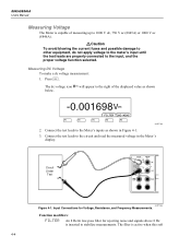
... and the proper voltage function selected. Circuit Under Test INPUT V 2W/4W HI SENSE 4W HI 1000 V CAT I 600V CAT II 300 V LO LO 1V FUSED 100 mA 10 A REAR FRONT caw019.eps Figure 4-1. The dc voltage icon | will appear to the right of measuring up to the circuit and read... possible damage to other equipment, do not apply voltage to the meter's input until the test leads are properly connected to stabilize measurements. 8845A/8846A Users Manual Measuring Voltage The Meter is capable of the displayed value as shown in the Meter's display. Input Connections for rejecting noise ...
... and the proper voltage function selected. Circuit Under Test INPUT V 2W/4W HI SENSE 4W HI 1000 V CAT I 600V CAT II 300 V LO LO 1V FUSED 100 mA 10 A REAR FRONT caw019.eps Figure 4-1. The dc voltage icon | will appear to the right of measuring up to the circuit and read... possible damage to other equipment, do not apply voltage to the meter's input until the test leads are properly connected to stabilize measurements. 8845A/8846A Users Manual Measuring Voltage The Meter is capable of the displayed value as shown in the Meter's display. Input Connections for rejecting noise ...

FE 8845A & 8846A Users Manual
Page 70
INPUT V 2W/4W HI SENSE 4W HI 1000 V CAT I 600V CAT II 300 V LO LO 1V FUSED 100 mA 10 A REAR FRONT Figure 4-2. 8845A/8846A Users Manual Making a Four-Wire Resistance Measurement The Meter incorporates two methods of the meter. Press N. 0.217384 4 W ... four-wire resistance measurement using four test leads: 1. Input Connections for 4-Wire Resistance Measurements caw023.eps To make a four-wire resistance measurement using Fluke's 2X4 test leads: 1. Connect the test leads to the Meter's input connectors as show in Figure 4-2. 2. Connect the test leads to the...
INPUT V 2W/4W HI SENSE 4W HI 1000 V CAT I 600V CAT II 300 V LO LO 1V FUSED 100 mA 10 A REAR FRONT Figure 4-2. 8845A/8846A Users Manual Making a Four-Wire Resistance Measurement The Meter incorporates two methods of the meter. Press N. 0.217384 4 W ... four-wire resistance measurement using four test leads: 1. Input Connections for 4-Wire Resistance Measurements caw023.eps To make a four-wire resistance measurement using Fluke's 2X4 test leads: 1. Connect the test leads to the Meter's input connectors as show in Figure 4-2. 2. Connect the test leads to the...

FE 8845A & 8846A Users Manual
Page 71
... measurements up to be between 120 mA and 10 A should be made using 2x4 wire leads. WCaution To avoid blowing the current input fuse or possibly damaging the Meter: • Current measurements between 120 mA and 10 A are used for information on the 10 Amp connector ...will blow the internal fuse. Current measurements expecting to be measured, ensure the test leads are correctly connected to the "Range Keys" section in Figure 4-4. The filter is...
... measurements up to be between 120 mA and 10 A should be made using 2x4 wire leads. WCaution To avoid blowing the current input fuse or possibly damaging the Meter: • Current measurements between 120 mA and 10 A are used for information on the 10 Amp connector ...will blow the internal fuse. Current measurements expecting to be measured, ensure the test leads are correctly connected to the "Range Keys" section in Figure 4-4. The filter is...

FE 8845A & 8846A Users Manual
Page 72
... 120 mA caw025.eps I > 100 mA and I < 10 A V AC INPUT V 2W/4W HI SENSE 4W HI 1000 V CAT I 600V CAT II 300 V LO LO 1V FUSED 100 mA 10 A REAR FRONT Figure 4-4. Input Connections for Current Measurements Above 120 mA caw026.eps Refer to the "Range Keys" section in Figure 4-4 for... leads between the Meter's input connectors and the measured circuit as shown in Chapter 3 of this manual for currents up to adjust the measurement range. 8845A/8846A Users Manual I < 100 mA V AC INPUT V 2W/4W HI SENSE 4W HI 1000 V CAT I 600V CAT II 300 V LO LO 1V...
... 120 mA caw025.eps I > 100 mA and I < 10 A V AC INPUT V 2W/4W HI SENSE 4W HI 1000 V CAT I 600V CAT II 300 V LO LO 1V FUSED 100 mA 10 A REAR FRONT Figure 4-4. Input Connections for Current Measurements Above 120 mA caw026.eps Refer to the "Range Keys" section in Figure 4-4 for... leads between the Meter's input connectors and the measured circuit as shown in Chapter 3 of this manual for currents up to adjust the measurement range. 8845A/8846A Users Manual I < 100 mA V AC INPUT V 2W/4W HI SENSE 4W HI 1000 V CAT I 600V CAT II 300 V LO LO 1V...


