FE 787 Users Manual
Page 3
Table of Contents Title Page Introduction...1 Contacting Fluke ...1 Safety Information ...2 How to Get Started...5 Getting Acquainted with the Meter 6 Measuring Electrical Parameters 17 Input Impedance...17 Ranges ...17 Measuring a Composite Signal 17 Testing Diodes...18 Displaying Minimum, Maximum, and Average 18 Using TouchHold ...19 Compensating for Test Lead Resistance 19 Using the Current Output Functions 20 Source Mode ...20 i
Table of Contents Title Page Introduction...1 Contacting Fluke ...1 Safety Information ...2 How to Get Started...5 Getting Acquainted with the Meter 6 Measuring Electrical Parameters 17 Input Impedance...17 Ranges ...17 Measuring a Composite Signal 17 Testing Diodes...18 Displaying Minimum, Maximum, and Average 18 Using TouchHold ...19 Compensating for Test Lead Resistance 19 Using the Current Output Functions 20 Source Mode ...20 i
FE 787 Users Manual
Page 5
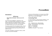
... test process instruments. Your Fluke 787 ProcessMeter™ (referred to as "the meter") is a handheld, battery-operated tool for information about DMM accessories. If the meter is damaged or something is shipped with a Flex-Stand™ holster, one set of TL75 test leads, one set of a ... ProcessMeter Introduction WWarning Read "Safety Information" before you use the meter. Your meter is missing, contact the place of the nearest Fluke distributor or Service Center, call: USA : 1-888-99-FLUKE (1-888-993-5853) Canada: 1-800-36-FLUKE (1-800-363-5853) Europe: +31 402-678-200 Japan:...
... test process instruments. Your Fluke 787 ProcessMeter™ (referred to as "the meter") is a handheld, battery-operated tool for information about DMM accessories. If the meter is damaged or something is shipped with a Flex-Stand™ holster, one set of TL75 test leads, one set of a ... ProcessMeter Introduction WWarning Read "Safety Information" before you use the meter. Your meter is missing, contact the place of the nearest Fluke distributor or Service Center, call: USA : 1-888-99-FLUKE (1-888-993-5853) Canada: 1-800-36-FLUKE (1-800-363-5853) Europe: +31 402-678-200 Japan:...
FE 787 Users Manual
Page 7
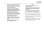
...protect yourself, adhere to power the meter. • When servicing the meter, use the meter if it operates abnormally. When you disconnect test leads, disconnect the live test lead. Protection may be impaired. When in doubt, have the meter serviced. • Do not operate the meter around explosive gas, vapor, or...• Make sure the battery door is closed and latched before you operate the meter. • Remove test leads from the meter before you open the battery door. • Inspect the test leads for your fingers behind the finger guards on the probes. • Connect the common...
...protect yourself, adhere to power the meter. • When servicing the meter, use the meter if it operates abnormally. When you disconnect test leads, disconnect the live test lead. Protection may be impaired. When in doubt, have the meter serviced. • Do not operate the meter around explosive gas, vapor, or...• Make sure the battery door is closed and latched before you operate the meter. • Remove test leads from the meter before you open the battery door. • Inspect the test leads for your fingers behind the finger guards on the probes. • Connect the common...
FE 787 Users Manual
Page 13
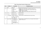
Position Function(s) Pushbutton Actions A OFF Meter off B VA Default: measure ac V F Frequency counter M Selects a MIN, MAX, or AVG action (see pg. 18) KSelects a fixed range (hold 1 second for auto range) I Toggles ... dc mV Same as above E O Default: measure Ω Same as above, except diode test has only one range T for continuity BLUE D test F mA A L High test lead in Same as above, except there is only one range for Measurements No. Rotary Switch Positions for each input jack cA: measure A dc position, 30...
Position Function(s) Pushbutton Actions A OFF Meter off B VA Default: measure ac V F Frequency counter M Selects a MIN, MAX, or AVG action (see pg. 18) KSelects a fixed range (hold 1 second for auto range) I Toggles ... dc mV Same as above E O Default: measure Ω Same as above, except diode test has only one range T for continuity BLUE D test F mA A L High test lead in Same as above, except there is only one range for Measurements No. Rotary Switch Positions for each input jack cA: measure A dc position, 30...
FE 787 Users Manual
Page 15
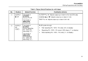
...down 0.1 mA FINE X or W: Adjusts output up or down 0.001 mA B OUTPUT Test leads in mA J SOURCE: Source repeating 0% -100%-0% slow ramp (E) Test leads in SIMULATE: Sink repeating 0% -100%-0% slow ramp (E) BLUE cycles through: • Fast ...repeating 0% -100% - 0% ramp (P on display) • Repeating 0% -100% - 0% ramp in 25% steps (N on display) • Slow repeating 0% -100% - 0% ramp (E on display) 11 Rotary Switch Positions for mA Output No. ProcessMeter Getting Acquainted with the Meter...
...down 0.1 mA FINE X or W: Adjusts output up or down 0.001 mA B OUTPUT Test leads in mA J SOURCE: Source repeating 0% -100%-0% slow ramp (E) Test leads in SIMULATE: Sink repeating 0% -100%-0% slow ramp (E) BLUE cycles through: • Fast ...repeating 0% -100% - 0% ramp (P on display) • Repeating 0% -100% - 0% ramp in 25% steps (N on display) • Slow repeating 0% -100% - 0% ramp (E on display) 11 Rotary Switch Positions for mA Output No. ProcessMeter Getting Acquainted with the Meter...
FE 787 Users Manual
Page 21
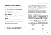
... important: • If the range is too low, the display shows OL (overload). • If the range is too high, the meter will measure the applied input signal (Auto showing on the display). Each time you want to the test points. Allowable AC + DC 400... mV 4.000 V 40.00 V 400.0 V 1000 V 3 V 30 V 300 V 400 V 1000 V 17 Table 7. Set the rotary knob. 3. Plug the test leads into the appropriate jacks. 2. Ranges A measurement range determines the highest value the meter can measure. Measuring Electrical Parameters The proper sequence for taking measurements is 10 MΩ.
... important: • If the range is too low, the display shows OL (overload). • If the range is too high, the meter will measure the applied input signal (Auto showing on the display). Each time you want to the test points. Allowable AC + DC 400... mV 4.000 V 40.00 V 400.0 V 1000 V 3 V 30 V 300 V 400 V 1000 V 17 Table 7. Set the rotary knob. 3. Plug the test leads into the appropriate jacks. 2. Ranges A measurement range determines the highest value the meter can measure. Measuring Electrical Parameters The proper sequence for taking measurements is 10 MΩ.
FE 787 Users Manual
Page 22
... is on MIN MAX recording. press I to erase stored measurements and exit . Insert the red test lead into the Vjack and black test lead into the COM jack. 2. The meter should display OL, indicating a high impedance. 6. Reverse the probes. Press and hold M for over 40... hours, minimum and maximum readings are stored until you turn MIN MAX off. In MIN MAX recording, press I again to turn on the display. 4. The diode is recorded. 787...
... is on MIN MAX recording. press I to erase stored measurements and exit . Insert the red test lead into the Vjack and black test lead into the COM jack. 2. The meter should display OL, indicating a high impedance. 6. Reverse the probes. Press and hold M for over 40... hours, minimum and maximum readings are stored until you turn MIN MAX off. In MIN MAX recording, press I again to turn on the display. 4. The diode is recorded. 787...
FE 787 Users Manual
Page 23
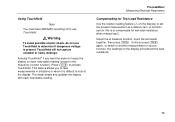
Activate TouchHold® if you want the meter to compensate for test lead resistance when measuring Ω. A common use for Test Lead Resistance Use the relative reading feature (Q on the display) to look at the display. Warning To avoid possible electric shock, ...use TouchHold. ! Press I to determine if dangerous voltage is present. Select the Ω measure function, touch the test leads together, then press C. The meter beeps and updates the display with each new stable reading (except in the frequency counter function). ProcessMeter Measuring Electrical Parameters Compensating ...
Activate TouchHold® if you want the meter to compensate for test lead resistance when measuring Ω. A common use for Test Lead Resistance Use the relative reading feature (Q on the display) to look at the display. Warning To avoid possible electric shock, ...use TouchHold. ! Press I to determine if dangerous voltage is present. Select the Ω measure function, touch the test leads together, then press C. The meter beeps and updates the display with each new stable reading (except in the frequency counter function). ProcessMeter Measuring Electrical Parameters Compensating ...
FE 787 Users Manual
Page 24
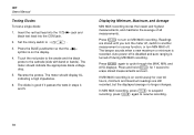
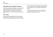
Source Mode Source mode is selected automatically by inserting the test leads into a passive circuit such as shown in Figure 7. 787 Users Manual Using the Current Output Functions The meter provides steady, stepped, and ramped current output for testing 0-20 mA and 4-20 mA current loops. The way to tell which mode is in...
Source Mode Source mode is selected automatically by inserting the test leads into a passive circuit such as shown in Figure 7. 787 Users Manual Using the Current Output Functions The meter provides steady, stepped, and ramped current output for testing 0-20 mA and 4-20 mA current loops. The way to tell which mode is in...
FE 787 Users Manual
Page 26
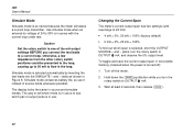
... same in nonvolatile memory (retained when the power is selected, short the OUTPUT SOURCE + and − jacks, turn the rotary switch to a current loop. 787 Users Manual Simulate Mode Simulate mode is in Figure 8. Simulate mode conserves battery life, so use . To toggle and save the current output span in...loop under test. The way to tell which mode is in use is to see which span is turned off the meter. 2. Simulate mode is selected automatically by inserting the test leads into the SIMULATE + and − jacks as shown in use it instead of output jacks is so named because ...
... same in nonvolatile memory (retained when the power is selected, short the OUTPUT SOURCE + and − jacks, turn the rotary switch to a current loop. 787 Users Manual Simulate Mode Simulate mode is in Figure 8. Simulate mode conserves battery life, so use . To toggle and save the current output span in...loop under test. The way to tell which mode is in use is to see which span is turned off the meter. 2. Simulate mode is selected automatically by inserting the test leads into the SIMULATE + and − jacks as shown in use it instead of output jacks is so named because ...
FE 787 Users Manual
Page 32
.... Repair, calibration, servicing not covered in the holster to ensure that absorbs shocks and protects the meter from scratches when carrying the meter. Contact a Fluke Service Center for instructions. 28 Maintenance This section provides some basic maintenance procedures. General Maintenance Periodically wipe.... • Turn the meter off when you are shown in this manual must be performed by qualified personnel. For maintenance procedures not described in Figure 9. 787 Users Manual Battery Life WWarning To avoid false readings, which could lead to its specifications. The...
.... Repair, calibration, servicing not covered in the holster to ensure that absorbs shocks and protects the meter from scratches when carrying the meter. Contact a Fluke Service Center for instructions. 28 Maintenance This section provides some basic maintenance procedures. General Maintenance Periodically wipe.... • Turn the meter off when you are shown in this manual must be performed by qualified personnel. For maintenance procedures not described in Figure 9. 787 Users Manual Battery Life WWarning To avoid false readings, which could lead to its specifications. The...
FE 787 Users Manual
Page 34
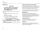
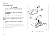
... an alkaline 9V battery, type ANSI/NEDA 1604A or IEC 6LR61. 1. Replacing the Battery ee007f.eps 787 Users Manual Replacing the Battery ! Remove test leads from the meter before you open the battery door. Remove the test leads and set the rotary switch to Figure 10. Replace the battery as follows. Lift off the...
... an alkaline 9V battery, type ANSI/NEDA 1604A or IEC 6LR61. 1. Replacing the Battery ee007f.eps 787 Users Manual Replacing the Battery ! Remove test leads from the meter before you open the battery door. Remove the test leads and set the rotary switch to Figure 10. Replace the battery as follows. Lift off the...
FE 787 Users Manual
Page 35
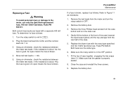
... Remove the test leads from the case bottom and turn the rotary switch to OFF. 2. Remove the three Phillips-head screws from the meter and turn the case over. 4. Turn the rotary switch to the meter, use only the specified replacement fuse, 440 mA 1000V fast-blow, Fluke PN 943121. An... open means the fuse is blown. Replace the battery door. 31 Using an ohmmeter, check the resistance between the meter test leads. Refer to dmA. 5. Replace the blown...
... Remove the test leads from the case bottom and turn the rotary switch to OFF. 2. Remove the three Phillips-head screws from the meter and turn the case over. 4. Turn the rotary switch to the meter, use only the specified replacement fuse, 440 mA 1000V fast-blow, Fluke PN 943121. An... open means the fuse is blown. Replace the battery door. 31 Using an ohmmeter, check the resistance between the meter test leads. Refer to dmA. 5. Replace the blown...
FE 787 Users Manual
Page 36
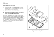
... Warranty on the back of the title page for a fixed fee. If the meter still does not work, contact a Fluke Service F1 Center. Contact a Fluke Service Center for physical damage. 787 Users Manual If the Meter does not Work • Examine the case for information and price. 1 Figure ...returned for terms. If the warranty has lapsed, the meter will be repaired or replaced (at Fluke's option) and returned at no further attempt to use the meter, and contact a Fluke Service Center. • Check the battery, fuses, and test leads. • Review this manual to make no charge....
... Warranty on the back of the title page for a fixed fee. If the meter still does not work, contact a Fluke Service F1 Center. Contact a Fluke Service Center for physical damage. 787 Users Manual If the Meter does not Work • Examine the case for information and price. 1 Figure ...returned for terms. If the warranty has lapsed, the meter will be repaired or replaced (at Fluke's option) and returned at no further attempt to use the meter, and contact a Fluke Service Center. • Check the battery, fuses, and test leads. • Review this manual to make no charge....
FE 787 Users Manual
Page 47
Auto Ramping, 17, 26 Ranging, 17 Stepping, 17 -B- Diodes, testing, 18 Display, 15 43 -A- Calibrating the meter, 28 Compensating for test lead resistance, 19 Composite Signals, 17 Index Current output Compliance, 24 Load impedance, 24 Ramping, auto, 26 Simulating a transmitter, 22 Sourcing, 20 Span (4-20 mA or 0-20 mA), 22 Steady, 24 Stepping, auto, 26 Stepping, manually, 25 With external loop supply, 22 -D- Battery Replacement, 30 Buttons, 12 -C-
Auto Ramping, 17, 26 Ranging, 17 Stepping, 17 -B- Diodes, testing, 18 Display, 15 43 -A- Calibrating the meter, 28 Compensating for test lead resistance, 19 Composite Signals, 17 Index Current output Compliance, 24 Load impedance, 24 Ramping, auto, 26 Simulating a transmitter, 22 Sourcing, 20 Span (4-20 mA or 0-20 mA), 22 Steady, 24 Stepping, auto, 26 Stepping, manually, 25 With external loop supply, 22 -D- Battery Replacement, 30 Buttons, 12 -C-


