
User Manual
Page 1
All product names are trademarks of their respective companies. All rights reserved. 438-II Motor Analyzer Users Manual March 2016 ©2016 Fluke Corporation.
All product names are trademarks of their respective companies. All rights reserved. 438-II Motor Analyzer Users Manual March 2016 ©2016 Fluke Corporation.

User Manual
Page 4
438-II Users Manual ii
438-II Users Manual ii

User Manual
Page 6
438-II Users Manual iv
438-II Users Manual iv

User Manual
Page 8
...8226; Power Adapter • Regional Power Cord • Safety Information (Multi-Language) • CD-ROM with local and national safety codes. Contact Fluke for more information about the kits that are dangerous to -mini USB B) • Soft Carry Case C1740 Additional kits are available that can be compromised...test. A Caution identifies conditions and procedures that include Flexible 6000 A AC Current Probes (set of Symbols used on the Product. 438-II Users Manual Safety Information A Warning identifies hazardous conditions and procedures that are available for the Motor Analyzer. 2
...8226; Power Adapter • Regional Power Cord • Safety Information (Multi-Language) • CD-ROM with local and national safety codes. Contact Fluke for more information about the kits that are dangerous to -mini USB B) • Soft Carry Case C1740 Additional kits are available that can be compromised...test. A Caution identifies conditions and procedures that include Flexible 6000 A AC Current Probes (set of Symbols used on the Product. 438-II Users Manual Safety Information A Warning identifies hazardous conditions and procedures that are available for the Motor Analyzer. 2

User Manual
Page 9
... Unbalance Derating Factor 0.7 to 1.0 0.1 indicative NA Harmonics Derating Factor 0.7 to 1.0 0.1 indicative NA Total NEMA Derating Factor 0.5 to obtain stable temperature. See Specifications in the Fluke 430 Series II Users Manual for at least 1 hour at stable operating temperature. Run the motor for the specifications of supported motors: Table 1. Table 2. Notes: • Rated torque is...
... Unbalance Derating Factor 0.7 to 1.0 0.1 indicative NA Harmonics Derating Factor 0.7 to 1.0 0.1 indicative NA Total NEMA Derating Factor 0.5 to obtain stable temperature. See Specifications in the Fluke 430 Series II Users Manual for at least 1 hour at stable operating temperature. Run the motor for the specifications of supported motors: Table 1. Table 2. Notes: • Rated torque is...
User Manual
Page 10
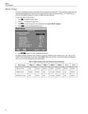
... Medium Breakdown Torque High Medium High Very High Medium High Medium 4 Push . Push to move through the menu selections and highlight Motor Analyzer. 4. 438-II Users Manual Motor Setup The motor nameplate provides information for measurements. Push to NEMA and IEC design types. The Motor Analyzer supports motor designs according to...
... Medium Breakdown Torque High Medium High Very High Medium High Medium 4 Push . Push to move through the menu selections and highlight Motor Analyzer. 4. 438-II Users Manual Motor Setup The motor nameplate provides information for measurements. Push to NEMA and IEC design types. The Motor Analyzer supports motor designs according to...

User Manual
Page 12
The limits you change the 50 Hz or 60 Hz DEFAULTS, go to the Motor Setup screen to red. 438-II Users Manual Unit Setup Use the setup screen to the previous screen. Softkeys: ANALYZER LIMITS 50 HZ DEFAULTS 60 HZ DEFAULTS BACK Sets ...
The limits you change the 50 Hz or 60 Hz DEFAULTS, go to the Motor Setup screen to red. 438-II Users Manual Unit Setup Use the setup screen to the previous screen. Softkeys: ANALYZER LIMITS 50 HZ DEFAULTS 60 HZ DEFAULTS BACK Sets ...

User Manual
Page 14
... turns from orange to red are set to the MOTOR SETUP screen. 2. For expert use, you can operate only at its rated efficiency at a glance. 438-II Users Manual Motor Analyzer Parameters The MOTOR ANALYZER screen shows the important mechanical and electrical parameters relative to show a good or bad indication because the motor can...
... turns from orange to red are set to the MOTOR SETUP screen. 2. For expert use, you can operate only at its rated efficiency at a glance. 438-II Users Manual Motor Analyzer Parameters The MOTOR ANALYZER screen shows the important mechanical and electrical parameters relative to show a good or bad indication because the motor can...

User Manual
Page 16
... unit no unit no unit Harmonic Power (k)VA Unbalance Power (k)VA Voltage (k)V Current (k)A Volt THD%x % Amp THD%x % Unbalance % 10 438-II Users Manual Meter Screen The METER screen shows all measurements in the 430 Series-II: Active Power (k)W Apparent Power (k)VA Reactive Power (k)var Power Factor no unit Cos φ/DPF no unit The other...
... unit no unit no unit Harmonic Power (k)VA Unbalance Power (k)VA Voltage (k)V Current (k)A Volt THD%x % Amp THD%x % Unbalance % 10 438-II Users Manual Meter Screen The METER screen shows all measurements in the 430 Series-II: Active Power (k)W Apparent Power (k)VA Reactive Power (k)var Power Factor no unit Cos φ/DPF no unit The other...

User Manual
Page 18
... are not equal, unbalanced currents in the stator windings will result in a much larger percentage of voltage unbalance will result. A small percentage of current unbalance. 438-II Users Manual NEMA Derating Screen NEMA has guidelines for motors with balanced voltages. The following derating curve is implemented in the power system. The NEMA standard MG...
... are not equal, unbalanced currents in the stator windings will result in a much larger percentage of voltage unbalance will result. A small percentage of current unbalance. 438-II Users Manual NEMA Derating Screen NEMA has guidelines for motors with balanced voltages. The following derating curve is implemented in the power system. The NEMA standard MG...

User Manual
Page 20
... ANALYZER screen. STOP measurements and save measurement results. 14 The green area indicates a motor that plots the cross-hair center in the Motor Setup screen). 438-II Users Manual The actual load and derating factor is indicated with . The red area indicates the overload area for the motor. The yellow area indicates...
... ANALYZER screen. STOP measurements and save measurement results. 14 The green area indicates a motor that plots the cross-hair center in the Motor Setup screen). 438-II Users Manual The actual load and derating factor is indicated with . The red area indicates the overload area for the motor. The yellow area indicates...
