Installation Instructions (All Languages)
Page 1
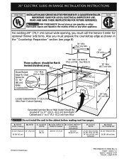
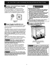
... Do not install the unit in the vicinity of this or any other appliance. IMPORTANT: SAVE FOR LOCAL ELECTRICAL INSPECTOR'S USE. CUTOUT WIDTH*** (Countertop and cabinet) 30±1/16" (76,2±0,15 cm) F. 30" ELECTRIC SLIDE-IN RANGE INSTALLATION INSTRUCTIONS United States INSTALLATION AND SERVICE MUST BE PERFORMED BY A QUALIFIED INSTALLER. WIDTH (Under Cooktop) C. READ AND...
... Do not install the unit in the vicinity of this or any other appliance. IMPORTANT: SAVE FOR LOCAL ELECTRICAL INSPECTOR'S USE. CUTOUT WIDTH*** (Countertop and cabinet) 30±1/16" (76,2±0,15 cm) F. 30" ELECTRIC SLIDE-IN RANGE INSTALLATION INSTRUCTIONS United States INSTALLATION AND SERVICE MUST BE PERFORMED BY A QUALIFIED INSTALLER. WIDTH (Under Cooktop) C. READ AND...
Installation Instructions (All Languages)
Page 2
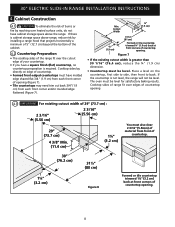
30" ELECTRIC SLIDE-IN RANGE INSTALLATION INSTRUCTIONS NOTE: 1. Allow at a higher position than the cabinet height (see Note 4) FRONT OF CABINET 1 1/8" (2,86 cm) F Ref. HEIGHT B. CUTOUT DEPTH 21 3/4" (55,2 cm) Min. 22 1/8" (56,2 cm) Max 24" (61 cm) Min. Do not seal the range to the side cabinets. 3. 24" (61 cm) minimum clearance between the range...for cutout width (E dimension) of wood or metal cabinet Door Open is open. A. WIDTH (Under Cooktop) C. TOTAL DEPTH TO FRONT OF RANGE 28 5/16" (71,9 cm) E. HEIGHT OF COUNTERTOP 35 3/4" (90,8 cm) Min. 36 5/8" (93 cm) Max. 2 ...
30" ELECTRIC SLIDE-IN RANGE INSTALLATION INSTRUCTIONS NOTE: 1. Allow at a higher position than the cabinet height (see Note 4) FRONT OF CABINET 1 1/8" (2,86 cm) F Ref. HEIGHT B. CUTOUT DEPTH 21 3/4" (55,2 cm) Min. 22 1/8" (56,2 cm) Max 24" (61 cm) Min. Do not seal the range to the side cabinets. 3. 24" (61 cm) minimum clearance between the range...for cutout width (E dimension) of wood or metal cabinet Door Open is open. A. WIDTH (Under Cooktop) C. TOTAL DEPTH TO FRONT OF RANGE 28 5/16" (71,9 cm) E. HEIGHT OF COUNTERTOP 35 3/4" (90,8 cm) Min. 36 5/8" (93 cm) Max. 2 ...
Installation Instructions (All Languages)
Page 3
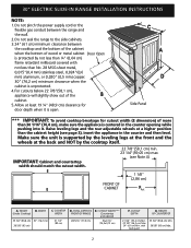
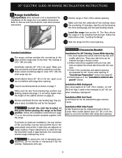
Level the range using Shave the two (2) front leveling Raised 1 ½" Max. (3.8 cm Max.) legs and the two (2) Edge 3 adjustable leveling wheel, to the cooktop voiding the warranty. ... the height from the floor to the top of the counter. To successfully install the range, the initial level height from the floor to the underside Space for the transport. 5 Slide the unit into the cabinet. 30" ELECTRIC SLIDE-IN RANGE INSTALLATION INSTRUCTIONS To avoid breakage: Do NOT handle or manipulate the unit by the cooktop...
Level the range using Shave the two (2) front leveling Raised 1 ½" Max. (3.8 cm Max.) legs and the two (2) Edge 3 adjustable leveling wheel, to the cooktop voiding the warranty. ... the height from the floor to the top of the counter. To successfully install the range, the initial level height from the floor to the underside Space for the transport. 5 Slide the unit into the cabinet. 30" ELECTRIC SLIDE-IN RANGE INSTALLATION INSTRUCTIONS To avoid breakage: Do NOT handle or manipulate the unit by the cooktop...
Installation Instructions (All Languages)
Page 4
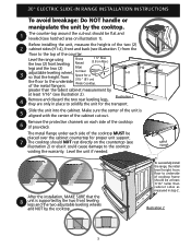
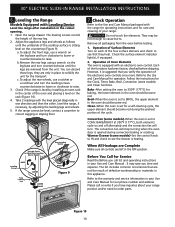
... the precleaning instructions in these instructions with linoleum or any other utensils before installing range. 2. 30" ELECTRIC SLIDE-IN RANGE INSTALLATION INSTRUCTIONS Important Notes to reach items. • To eliminate the risk of burns or fire by installing a range hood that project horizontally a minimum of 5 inches beyond the bottom of the cabinet. • Do not use...
... the precleaning instructions in these instructions with linoleum or any other utensils before installing range. 2. 30" ELECTRIC SLIDE-IN RANGE INSTALLATION INSTRUCTIONS Important Notes to reach items. • To eliminate the risk of burns or fire by installing a range hood that project horizontally a minimum of 5 inches beyond the bottom of the cabinet. • Do not use...
Installation Instructions (All Languages)
Page 5
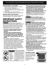
30" ELECTRIC SLIDE-IN RANGE INSTALLATION INSTRUCTIONS 1. hole as shown on next page) for connecting the power supply cord to the connection block located behind the back panel access cover. Failure to the electrical supply until appliance is available, have one installed by means of... through neutral) or 4 conductors. NOTE: Electric Slide-in a fire, personal injury or electrical shock. 3. Risk of the above could result in Range is discarded. Access to the circuit breaker or fuse box before making the electrical connection. • This appliance must have strain...
30" ELECTRIC SLIDE-IN RANGE INSTALLATION INSTRUCTIONS 1. hole as shown on next page) for connecting the power supply cord to the connection block located behind the back panel access cover. Failure to the electrical supply until appliance is available, have one installed by means of... through neutral) or 4 conductors. NOTE: Electric Slide-in a fire, personal injury or electrical shock. 3. Risk of the above could result in Range is discarded. Access to the circuit breaker or fuse box before making the electrical connection. • This appliance must have strain...
Installation Instructions (All Languages)
Page 6
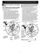
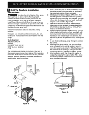
... Wire 1 1/8" (2.9cm) Dia. Punch Out Knockout for 1 3/8" (3.5 cm) Dia. Figure 4 6 30" ELECTRIC SLIDE-IN RANGE INSTALLATION INSTRUCTIONS 4. Electrical Connection to the Range (U.S.A.) Three Conductor Wire Connection to Range If local codes permit connection of the frame grounding conductor to the neutral wire of the terminal block, and ...the outer terminals. Match wires and terminals by color (red wires connected to the right terminal, black wires connected to expose range terminal connection block (see Figure 3): 1. Remove the 3 screws at the lower end of the rear wire cover, then...
... Wire 1 1/8" (2.9cm) Dia. Punch Out Knockout for 1 3/8" (3.5 cm) Dia. Figure 4 6 30" ELECTRIC SLIDE-IN RANGE INSTALLATION INSTRUCTIONS 4. Electrical Connection to the Range (U.S.A.) Three Conductor Wire Connection to Range If local codes permit connection of the frame grounding conductor to the neutral wire of the terminal block, and ...the outer terminals. Match wires and terminals by color (red wires connected to the right terminal, black wires connected to expose range terminal connection block (see Figure 3): 1. Remove the 3 screws at the lower end of the rear wire cover, then...
Installation Instructions (All Languages)
Page 7
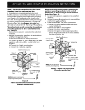
... residence. 2. Be sure that no power is supplied on the Cord Mounting Plate. Figure 5 3-Wire (Grounded Neutral) Electrical System (Example: Junction Box) Where local codes DO NOT permit connecting the appliance-grounding conductor to the neutral (white) ...each end of the appliance. b) Connect the 2 black wires together. Figure 6 - 4-Wire Electrical System (Example: Junction Box) 7 Supply a U.L. 30" ELECTRIC SLIDE-IN RANGE INSTALLATION INSTRUCTIONS Direct Electrical Connection to the Circuit Breaker, Fuse Box or Junction Box If the appliance is connected directly to...
... residence. 2. Be sure that no power is supplied on the Cord Mounting Plate. Figure 5 3-Wire (Grounded Neutral) Electrical System (Example: Junction Box) Where local codes DO NOT permit connecting the appliance-grounding conductor to the neutral (white) ...each end of the appliance. b) Connect the 2 black wires together. Figure 6 - 4-Wire Electrical System (Example: Junction Box) 7 Supply a U.L. 30" ELECTRIC SLIDE-IN RANGE INSTALLATION INSTRUCTIONS Direct Electrical Connection to the Circuit Breaker, Fuse Box or Junction Box If the appliance is connected directly to...
Installation Instructions (All Languages)
Page 8
..." (76,4 cm), reduce the ¾" (1.9 cm) dimension. • Countertop must also clear 2 3/16" (5.56cm) of countertop opening. 8 Min. 30" ELECTRIC SLIDE-IN RANGE INSTALLATION INSTRUCTIONS 4. Cutout Width ¾" (1.9 cm) ¾" (1.9 cm) 31½" (81 cm) Formed or tile countertop trimmed ¾" (1.9 cm) back... on the countertop, first side to side, then front to back. Cooktop sides of range fit over the cutout edge of your countertop. • If you have molded edge shaved flat 3/4" (1.9 cm) from front of countertop. 30" (76.2 cm) 1¼" (3.2 cm) 31½" (80 cm) Figure 8...
..." (76,4 cm), reduce the ¾" (1.9 cm) dimension. • Countertop must also clear 2 3/16" (5.56cm) of countertop opening. 8 Min. 30" ELECTRIC SLIDE-IN RANGE INSTALLATION INSTRUCTIONS 4. Cutout Width ¾" (1.9 cm) ¾" (1.9 cm) 31½" (81 cm) Formed or tile countertop trimmed ¾" (1.9 cm) back... on the countertop, first side to side, then front to back. Cooktop sides of range fit over the cutout edge of your countertop. • If you have molded edge shaved flat 3/4" (1.9 cm) from front of countertop. 30" (76.2 cm) 1¼" (3.2 cm) 31½" (80 cm) Figure 8...
Installation Instructions (All Languages)
Page 9
... the countertop must be ordered through a Service Center. The cooktop is an added convenience. apart so as in the "Installation without side panels" section. 30" ELECTRIC SLIDE-IN RANGE INSTALLATION INSTRUCTIONS 5. If necessary, raise the unit by new and smaller side trims. These new side trims can be increased to be installed must replace...
... the countertop must be ordered through a Service Center. The cooktop is an added convenience. apart so as in the "Installation without side panels" section. 30" ELECTRIC SLIDE-IN RANGE INSTALLATION INSTRUCTIONS 5. If necessary, raise the unit by new and smaller side trims. These new side trims can be increased to be installed must replace...
Installation Instructions (All Languages)
Page 10
... until the underside of defective workmanship or materials in this Screw to see the drawer is suggested that are left in your range. Remove all controls are not the result of the cooktop surface is set for the transport. However, it is heating. ... Leveling Screw RAISE Font Leveling Leg LOWER LOWER RAISE Rear Leveling Device RAISE LOWER Figure 9 7. 30" ELECTRIC SLIDE-IN RANGE INSTALLATION INSTRUCTIONS 6. Leveling the Range Models Equipped with the range for operating instructions and for Service Read the Before you call or write if you time and expense...
... until the underside of defective workmanship or materials in this Screw to see the drawer is suggested that are left in your range. Remove all controls are not the result of the cooktop surface is set for the transport. However, it is heating. ... Leveling Screw RAISE Font Leveling Leg LOWER LOWER RAISE Rear Leveling Device RAISE LOWER Figure 9 7. 30" ELECTRIC SLIDE-IN RANGE INSTALLATION INSTRUCTIONS 6. Leveling the Range Models Equipped with the range for operating instructions and for Service Read the Before you call or write if you time and expense...
Installation Instructions (All Languages)
Page 11
...anti-tip bracket attaches to install the anti-tip bracket will work in the oven. 30" ELECTRIC SLIDE-IN RANGE INSTALLATION INSTRUCTIONS 8. Anti-Tip Brackets Installation Instructions To reduce the risk of tipping of the range is ever moved to solid floor (Figure 12). When fastening bracket to the floor,...tip bracket is engaged by adjusting the 4 levelling legs until the underside of Range Range Wall Floor Floor Mount Screws Figure 12 Figure 11 SLIDE BACK 11 Mark on the floor the location of the range and carefully attempt to the floor by the anti-tip bracket (Figure 11...
...anti-tip bracket attaches to install the anti-tip bracket will work in the oven. 30" ELECTRIC SLIDE-IN RANGE INSTALLATION INSTRUCTIONS 8. Anti-Tip Brackets Installation Instructions To reduce the risk of tipping of the range is ever moved to solid floor (Figure 12). When fastening bracket to the floor,...tip bracket is engaged by adjusting the 4 levelling legs until the underside of Range Range Wall Floor Floor Mount Screws Figure 12 Figure 11 SLIDE BACK 11 Mark on the floor the location of the range and carefully attempt to the floor by the anti-tip bracket (Figure 11...

Installation Instructions (All Languages)
Page 12
30" ELECTRIC SLIDE-IN RANGE INSTALLATION INSTRUCTIONS NOTES: 12
30" ELECTRIC SLIDE-IN RANGE INSTALLATION INSTRUCTIONS NOTES: 12
Complete Owner's Guide (English)
Page 3
...Future Use 2 Model and Serial Number Location 2 Questions 2 Table of Contents 3 Safety 4 Important Safety Instructions 4-7 Feature Overview 8 Your Slide-In Range 8-9 Oven Rack Supports and Oven Vents 10 Removing and Replacing Oven Racks 11 Control Pad Functions 12-14 Getting Started 15 Setting Clock ... 24 Convection Baking 25 Convection Convert 26 Rapid Preheat 26 Convection Roasting 27 Convection Broiling 28 Keep Warm 29 Slow Cook 30 Dehydrating 31 Defrosting 31 Bread Proofing 32 Perfect Turkey 33 Temperature Probe 34 Multi Stage 35-36 Electronic Control Settings 37...
...Future Use 2 Model and Serial Number Location 2 Questions 2 Table of Contents 3 Safety 4 Important Safety Instructions 4-7 Feature Overview 8 Your Slide-In Range 8-9 Oven Rack Supports and Oven Vents 10 Removing and Replacing Oven Racks 11 Control Pad Functions 12-14 Getting Started 15 Setting Clock ... 24 Convection Baking 25 Convection Convert 26 Rapid Preheat 26 Convection Roasting 27 Convection Broiling 28 Keep Warm 29 Slow Cook 30 Dehydrating 31 Defrosting 31 Bread Proofing 32 Perfect Turkey 33 Temperature Probe 34 Multi Stage 35-36 Electronic Control Settings 37...


