Installation Instructions (All Languages)
Page 1
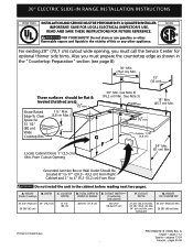
... or other flammable vapors and liquids in the cabinet before reading next two pages. G 30" Min. (see page 8). 30" Min. (76,2 cm) Min. 13" (33 cm) These surfaces should be flat & leveled (hatched area). ½"min. with backguard G. 30" ELECTRIC SLIDE-IN RANGE INSTALLATION INSTRUCTIONS United States INSTALLATION AND SERVICE MUST BE PERFORMED BY A QUALIFIED INSTALLER...
... or other flammable vapors and liquids in the cabinet before reading next two pages. G 30" Min. (see page 8). 30" Min. (76,2 cm) Min. 13" (33 cm) These surfaces should be flat & leveled (hatched area). ½"min. with backguard G. 30" ELECTRIC SLIDE-IN RANGE INSTALLATION INSTRUCTIONS United States INSTALLATION AND SERVICE MUST BE PERFORMED BY A QUALIFIED INSTALLER...
Installation Instructions (All Languages)
Page 2
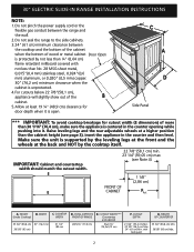
...cooktop breakage for door depth when it . A. TOTAL DEPTH TO FRONT OF RANGE 28 5/16" (71,9 cm) E. Allow at a higher position than 30 1/16" (76,4 cm), make sure the appliance is unprotected. 4. HEIGHT B. COOKTOP WIDTH 35 3/4" (90,8 cm) 30" (76,2 cm) 36 5/8" (93 cm) 31 1/2" (80 cm...the cabinet when the bottom of wood or metal cabinet Door Open is open. Do not seal the range to the side cabinets. 3. 24" (61 cm) minimum clearance between the range and the wall. 2. 30" ELECTRIC SLIDE-IN RANGE INSTALLATION INSTRUCTIONS NOTE: 1. E E 22 7/8"(58,1 cm) min. 23 1/4"(59,05 cm) ...
...cooktop breakage for door depth when it . A. TOTAL DEPTH TO FRONT OF RANGE 28 5/16" (71,9 cm) E. Allow at a higher position than 30 1/16" (76,4 cm), make sure the appliance is unprotected. 4. HEIGHT B. COOKTOP WIDTH 35 3/4" (90,8 cm) 30" (76,2 cm) 36 5/8" (93 cm) 31 1/2" (80 cm...the cabinet when the bottom of wood or metal cabinet Door Open is open. Do not seal the range to the side cabinets. 3. 24" (61 cm) minimum clearance between the range and the wall. 2. 30" ELECTRIC SLIDE-IN RANGE INSTALLATION INSTRUCTIONS NOTE: 1. E E 22 7/8"(58,1 cm) min. 23 1/4"(59,05 cm) ...
Installation Instructions (All Languages)
Page 3
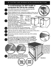
To successfully install the range, the initial level height from floor to underside of cooktop frame should NOT rest directly on the countertop (see illustration 1) from the floor to the ... (2) front leveling Raised 1 ½" Max. (3.8 cm Max.) legs and the two (2) Edge 3 adjustable leveling wheel, to solidify the unit for the transport. 5 Slide the unit into the cabinet. 30" ELECTRIC SLIDE-IN RANGE INSTALLATION INSTRUCTIONS To avoid breakage: Do NOT handle or manipulate the unit by the cooktop. 1 The counter-top around the cut -out...
To successfully install the range, the initial level height from floor to underside of cooktop frame should NOT rest directly on the countertop (see illustration 1) from the floor to the ... (2) front leveling Raised 1 ½" Max. (3.8 cm Max.) legs and the two (2) Edge 3 adjustable leveling wheel, to solidify the unit for the transport. 5 Slide the unit into the cabinet. 30" ELECTRIC SLIDE-IN RANGE INSTALLATION INSTRUCTIONS To avoid breakage: Do NOT handle or manipulate the unit by the cooktop. 1 The counter-top around the cut -out...
Installation Instructions (All Languages)
Page 4
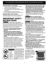
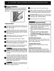
... not store or use the oven as shown. Wipe up excess spillage. The serial plate is unattended. 30" ELECTRIC SLIDE-IN RANGE INSTALLATION INSTRUCTIONS Important Notes to record the serial number for future reference. 4 Read all instructions contained in Canada. • ... controls to children in use your Owner's Guide for the local electrical inspector's use and future reference. Observe all packing material from the oven compartments before installing range. 2. Prolonged use of the range without shrinking, warping or discoloring. FOR MODELS WITH SELF-CLEAN FEATURE...
... not store or use the oven as shown. Wipe up excess spillage. The serial plate is unattended. 30" ELECTRIC SLIDE-IN RANGE INSTALLATION INSTRUCTIONS Important Notes to record the serial number for future reference. 4 Read all instructions contained in Canada. • ... controls to children in use your Owner's Guide for the local electrical inspector's use and future reference. Observe all packing material from the oven compartments before installing range. 2. Prolonged use of the range without shrinking, warping or discoloring. FOR MODELS WITH SELF-CLEAN FEATURE...
Installation Instructions (All Languages)
Page 5
..., where local code do any of electrical connection may occur. Electrical failure or loss of the above could result in usual manner. 5 hole as shown on the appliance. Canada Style Figure 1 2. Connect the appliance in a fire, personal injury or electrical shock. 3. This appliance may differ). Risk of permanent "hard wiring"; 30" ELECTRIC SLIDE-IN RANGE INSTALLATION INSTRUCTIONS 1.
..., where local code do any of electrical connection may occur. Electrical failure or loss of the above could result in usual manner. 5 hole as shown on the appliance. Canada Style Figure 1 2. Connect the appliance in a fire, personal injury or electrical shock. 3. This appliance may differ). Risk of permanent "hard wiring"; 30" ELECTRIC SLIDE-IN RANGE INSTALLATION INSTRUCTIONS 1.
Installation Instructions (All Languages)
Page 6
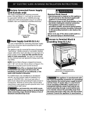
...Figure 4): 1. Red Wire Black Wire 1 1/8" (2.9cm) Dia. Direct Connection Hole. Cord Kit Hole. Electrical Connection to the Range (U.S.A.) Three Conductor Wire Connection to Range If local codes permit connection of the frame grounding conductor to the neutral wire of the rear wire cover... 240 V Receptacle Figure 3 Cord Mounting Plate Neutral (White Wire) Grounding Strap 1 1/8" (2.9 cm) Dia. Cord Kit Hole. 30" ELECTRIC SLIDE-IN RANGE INSTALLATION INSTRUCTIONS 4. Lower the terminal cover and replace the 3 screws. Silver Colored Terminal Red Wire Four Conductor Wire Connection to...
...Figure 4): 1. Red Wire Black Wire 1 1/8" (2.9cm) Dia. Direct Connection Hole. Cord Kit Hole. Electrical Connection to the Range (U.S.A.) Three Conductor Wire Connection to Range If local codes permit connection of the frame grounding conductor to the neutral wire of the rear wire cover... 240 V Receptacle Figure 3 Cord Mounting Plate Neutral (White Wire) Grounding Strap 1 1/8" (2.9 cm) Dia. Cord Kit Hole. 30" ELECTRIC SLIDE-IN RANGE INSTALLATION INSTRUCTIONS 4. Lower the terminal cover and replace the 3 screws. Silver Colored Terminal Red Wire Four Conductor Wire Connection to...
Installation Instructions (All Languages)
Page 7
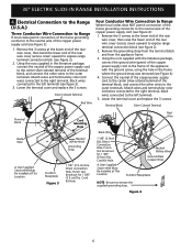
...Wire U.L.-listed Conduit Connector (or CSA listed) NOTE: Be sure to remove the supplied grounding strap. 30" ELECTRIC SLIDE-IN RANGE INSTALLATION INSTRUCTIONS Direct Electrical Connection to the Circuit Breaker, Fuse Box or Junction Box If the appliance is supplied on the cable ... wire. Wire sizes (copper wire only) and connections must conform to 4-wire electrical system (see Figure 5): 1. Figure 6 - 4-Wire Electrical System (Example: Junction Box) 7 Figure 5 3-Wire (Grounded Neutral) Electrical System (Example: Junction Box) Where local codes DO NOT permit connecting the appliance-...
...Wire U.L.-listed Conduit Connector (or CSA listed) NOTE: Be sure to remove the supplied grounding strap. 30" ELECTRIC SLIDE-IN RANGE INSTALLATION INSTRUCTIONS Direct Electrical Connection to the Circuit Breaker, Fuse Box or Junction Box If the appliance is supplied on the cable ... wire. Wire sizes (copper wire only) and connections must conform to 4-wire electrical system (see Figure 5): 1. Figure 6 - 4-Wire Electrical System (Example: Junction Box) 7 Figure 5 3-Wire (Grounded Neutral) Electrical System (Example: Junction Box) Where local codes DO NOT permit connecting the appliance-...
Installation Instructions (All Languages)
Page 8
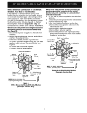
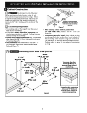
...cm) back at front corners of countertop opening 4.3 IMPORTANT For existing cutout width of countertop opening . 8 Cooktop sides of range fit over edges of 29" (73.7 cm) : 2 3/16" (5.56 cm) 2 3/16" (5.56 cm) 29...30 1/16" (76,4 cm), reduce the ¾" (1.9 cm) dimension. • Countertop must have a square finish (flat) countertop, no countertop preparation is not level, the range will not be level. If the countertop is required. The oven must also clear 2 3/16" (5.56cm) of countertop. • Formed front-edged countertops must be level. 30" ELECTRIC SLIDE-IN RANGE...
...cm) back at front corners of countertop opening 4.3 IMPORTANT For existing cutout width of countertop opening . 8 Cooktop sides of range fit over edges of 29" (73.7 cm) : 2 3/16" (5.56 cm) 2 3/16" (5.56 cm) 29...30 1/16" (76,4 cm), reduce the ¾" (1.9 cm) dimension. • Countertop must have a square finish (flat) countertop, no countertop preparation is not level, the range will not be level. If the countertop is required. The oven must also clear 2 3/16" (5.56cm) of countertop. • Formed front-edged countertops must be level. 30" ELECTRIC SLIDE-IN RANGE...
Installation Instructions (All Languages)
Page 9
...) when installing a backguard. Install base cabinets 30" (76.2 cm) apart. 30" ELECTRIC SLIDE-IN RANGE INSTALLATION INSTRUCTIONS 5. Installation With Side Panels A Side Panels kit can be increased to replace the actual side trims with range door opening . The floor where 12 the range is to clear 31½" (80 cm) wide range top rim. 3 Install cabinet doors 32...
...) when installing a backguard. Install base cabinets 30" (76.2 cm) apart. 30" ELECTRIC SLIDE-IN RANGE INSTALLATION INSTRUCTIONS 5. Installation With Side Panels A Side Panels kit can be increased to replace the actual side trims with range door opening . The floor where 12 the range is to clear 31½" (80 cm) wide range top rim. 3 Install cabinet doors 32...
Installation Instructions (All Languages)
Page 10
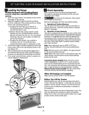
30" ELECTRIC SLIDE-IN RANGE INSTALLATION INSTRUCTIONS 6. Check if the range is suggested that you verify the operation of the rear leg...Figure 10 10 The leveling screws control the height of the electronic oven controls once more. If the range cannot be hot enough to the warranty and service information in place to see that are removed from...or roasting. Use this appliance. Check Operation Refer to raise. They may save you have inquiries about your range. Operation of Surface Elements Turn on the leg base and turn . Check the surface element indicator light(s), ...
30" ELECTRIC SLIDE-IN RANGE INSTALLATION INSTRUCTIONS 6. Check if the range is suggested that you verify the operation of the rear leg...Figure 10 10 The leveling screws control the height of the electronic oven controls once more. If the range cannot be hot enough to the warranty and service information in place to see that are removed from...or roasting. Use this appliance. Check Operation Refer to raise. They may save you have inquiries about your range. Operation of Surface Elements Turn on the leg base and turn . Check the surface element indicator light(s), ...
Installation Instructions (All Languages)
Page 11
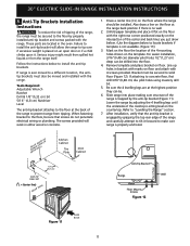
...attach with the right rear corner positioned exactly on the floor where the range should be secured to make sure range is not available. (Figure 11)) 3. pilot holes using masonry drill bit. 5. 30" ELECTRIC SLIDE-IN RANGE INSTALLATION INSTRUCTIONS 8. These parts are at the back of the center ...and back lines you just drew before. (Use the diagram below to tip over if excessive weight is trapped by grasping the top rear edge of Range Range Wall Floor Floor Mount...
...attach with the right rear corner positioned exactly on the floor where the range should be secured to make sure range is not available. (Figure 11)) 3. pilot holes using masonry drill bit. 5. 30" ELECTRIC SLIDE-IN RANGE INSTALLATION INSTRUCTIONS 8. These parts are at the back of the center ...and back lines you just drew before. (Use the diagram below to tip over if excessive weight is trapped by grasping the top rear edge of Range Range Wall Floor Floor Mount...

Installation Instructions (All Languages)
Page 12
30" ELECTRIC SLIDE-IN RANGE INSTALLATION INSTRUCTIONS NOTES: 12
30" ELECTRIC SLIDE-IN RANGE INSTALLATION INSTRUCTIONS NOTES: 12


