User Manual
Page 4
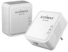
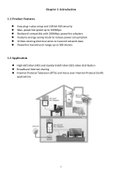
... Features energy saving mode to reduce power consumption Utilizes existing electrical wires to transmit network data Powerline transmission range up to 300 meters 1.2 Application High-definition (HD) and standard-definition (SD) video distribution Broadband Internet sharing Internet Protocol Television (...
... Features energy saving mode to reduce power consumption Utilizes existing electrical wires to transmit network data Powerline transmission range up to 300 meters 1.2 Application High-definition (HD) and standard-definition (SD) video distribution Broadband Internet sharing Internet Protocol Television (...
User Manual
Page 5
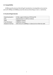
1.3 Compatibility AV500 powerline devices (HomePlug AV standard) are incompatible and cannot be used with 14Mbps and 85Mbps powerline devices (HomePlug 1.0 and 1.1 standards). 1.4 System Requirements Operating System CPU RAM Free Disk Space Network Interface Utility supports Windows XP/Vista/7/8 Intel Pentium III 1.0GHz (or above) 256MB (or above) 100MB (or above) Ethernet port (100Mbps or above) and an Ethernet cable 4
1.3 Compatibility AV500 powerline devices (HomePlug AV standard) are incompatible and cannot be used with 14Mbps and 85Mbps powerline devices (HomePlug 1.0 and 1.1 standards). 1.4 System Requirements Operating System CPU RAM Free Disk Space Network Interface Utility supports Windows XP/Vista/7/8 Intel Pentium III 1.0GHz (or above) 256MB (or above) 100MB (or above) Ethernet port (100Mbps or above) and an Ethernet cable 4
User Manual
Page 6
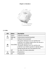
Chapter 2: Interfaces 2.1 LEDs LED Status Description Green LAN port connected LAN Blinking Off LAN activity (transferring data) LAN port not connected The green indicator turns on and the red indicator turns blinks slowly when the device is being transferred over the powerline link. Off No other PLC device detected Green Powered on and the red indicator turns blinks quickly to indicate data is PLC Green/Red detecting a powerline link. The green indicator turns on PWR Off Powered off 5
Chapter 2: Interfaces 2.1 LEDs LED Status Description Green LAN port connected LAN Blinking Off LAN activity (transferring data) LAN port not connected The green indicator turns on and the red indicator turns blinks slowly when the device is being transferred over the powerline link. Off No other PLC device detected Green Powered on and the red indicator turns blinks quickly to indicate data is PLC Green/Red detecting a powerline link. The green indicator turns on PWR Off Powered off 5
User Manual
Page 7
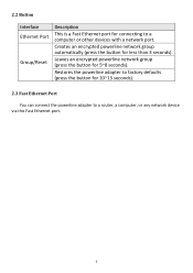
Leaves an encrypted powerline network group (press the button for less than 3 seconds). Restores the powerline adapter to factory defaults (press the button for 10~15 seconds). 2.3 Fast Ethernet Port You can connect the powerline adapter to a computer or other devices with a network port. Creates an encrypted powerline network group automatically (press the button for 5~8 seconds). 2.2 Button Interface Ethernet Port Group/Reset Description This is a Fast Ethernet port for connecting to a router, a computer, or any network device via this Fast Ethernet port. 6
Leaves an encrypted powerline network group (press the button for less than 3 seconds). Restores the powerline adapter to factory defaults (press the button for 10~15 seconds). 2.3 Fast Ethernet Port You can connect the powerline adapter to a computer or other devices with a network port. Creates an encrypted powerline network group automatically (press the button for 5~8 seconds). 2.2 Button Interface Ethernet Port Group/Reset Description This is a Fast Ethernet port for connecting to a router, a computer, or any network device via this Fast Ethernet port. 6
User Manual
Page 8
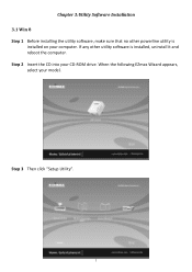
When the following EZmax Wizard appears, select your CD-ROM drive. If any other powerline utility is installed, uninstall it and reboot the computer. Step 2 Insert the CD into your model. Step 3 Then click "Setup Utility". 7 Chapter 3:Utility Software Installation 3.1 Win 8 Step 1 Before installing the utility software, make sure that no other utility software is installed on your computer.
When the following EZmax Wizard appears, select your CD-ROM drive. If any other powerline utility is installed, uninstall it and reboot the computer. Step 2 Insert the CD into your model. Step 3 Then click "Setup Utility". 7 Chapter 3:Utility Software Installation 3.1 Win 8 Step 1 Before installing the utility software, make sure that no other utility software is installed on your computer.

User Manual
Page 12
Step 9 Click the "Edimax PowerLine Utility", the "PLC 500Mbps Utility" appears, click "Next" to continue. 11
Step 9 Click the "Edimax PowerLine Utility", the "PLC 500Mbps Utility" appears, click "Next" to continue. 11
User Manual
Page 14
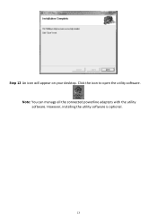
Step 12 An icon will appear on your desktop. However, installing the utility software is optional. 13 Note: You can manage all the connected powerline adapters with the utility software. Click the icon to open the utility software.
Step 12 An icon will appear on your desktop. However, installing the utility software is optional. 13 Note: You can manage all the connected powerline adapters with the utility software. Click the icon to open the utility software.
User Manual
Page 15
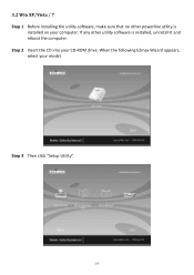
If any other powerline utility is installed, uninstall it and reboot the computer. When the following EZmax Wizard appears, select your CD-ROM drive. Step 2 Insert the CD into your model. Step 3 Then click "Setup Utility". 14 3.2 Win XP/Vista / 7 Step 1 Before installing the utility software, make sure that no other utility software is installed on your computer.
If any other powerline utility is installed, uninstall it and reboot the computer. When the following EZmax Wizard appears, select your CD-ROM drive. Step 2 Insert the CD into your model. Step 3 Then click "Setup Utility". 14 3.2 Win XP/Vista / 7 Step 1 Before installing the utility software, make sure that no other utility software is installed on your computer.
User Manual
Page 18
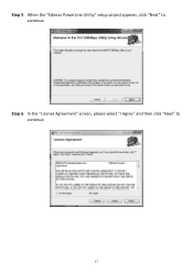
Step 6 In the "License Agreement" screen, please select "I Agree" and then click "Next" to continue. Step 5 When the "Edimax PowerLine Utility" setup wizard appears, click "Next" to continue. 17
Step 6 In the "License Agreement" screen, please select "I Agree" and then click "Next" to continue. Step 5 When the "Edimax PowerLine Utility" setup wizard appears, click "Next" to continue. 17

User Manual
Page 20
Click the icon to open the utility software. Note: You can manage all the connected powerline adapters with the utility software. Step 10 An icon will appear on your desktop. However, installing the utility software is complete, click "Close". Step 9 After the installation is optional. 19
Click the icon to open the utility software. Note: You can manage all the connected powerline adapters with the utility software. Step 10 An icon will appear on your desktop. However, installing the utility software is complete, click "Close". Step 9 After the installation is optional. 19
User Manual
Page 21
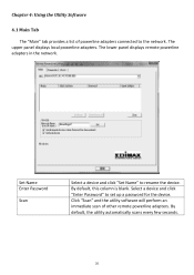
...and click "Set Name" to the network. The upper panel displays local powerline adapters. By default, this column is blank. Chapter 4: Using the Utility Software 4.1 Main Tab The "Main" tab provides a list of other remote powerline adapters. Select a device and click "Enter Password" to set up ...a password for the device. Click "Scan" and the utility software will perform an immediate scan of powerline adapters connected to rename the device. By default, the...
...and click "Set Name" to the network. The upper panel displays local powerline adapters. By default, this column is blank. Chapter 4: Using the Utility Software 4.1 Main Tab The "Main" tab provides a list of other remote powerline adapters. Select a device and click "Enter Password" to set up ...a password for the device. Click "Scan" and the utility software will perform an immediate scan of powerline adapters connected to rename the device. By default, the...
User Manual
Page 24
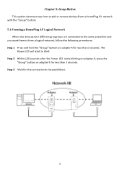
... from a HomePlug AV network with the "Group" button. 5.1 Forming a HomePlug AV Logical Network When two devices with different group keys are connected to the same powerline and you want them to form a logical network, follow the following procedures: Step 1 Press and hold the "Group" button on adapter B for less than 3 seconds...
... from a HomePlug AV network with the "Group" button. 5.1 Forming a HomePlug AV Logical Network When two devices with different group keys are connected to the same powerline and you want them to form a logical network, follow the following procedures: Step 1 Press and hold the "Group" button on adapter B for less than 3 seconds...
User Manual
Page 25
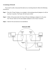
Step 2 Within 120 seconds after the Power LED starts blinking on adapter A or B, press the "Group" button on an adapter in the existing network (adapter A or B) for at least 3 seconds. Step 3 Wait for the connection to an existing network, follow the following procedures: Step 1 Press the "Group" button on the new adapter (adapter C) for less than 3 seconds. 5.2 Joining a Network If you want to add a new powerline device to be established. 24 The Power LED will start to blink.
Step 2 Within 120 seconds after the Power LED starts blinking on adapter A or B, press the "Group" button on an adapter in the existing network (adapter A or B) for at least 3 seconds. Step 3 Wait for the connection to an existing network, follow the following procedures: Step 1 Press the "Group" button on the new adapter (adapter C) for less than 3 seconds. 5.2 Joining a Network If you want to add a new powerline device to be established. 24 The Power LED will start to blink.

User Manual
Page 26
... on adapter B for at least 10 seconds. Step 2 Wait for adapter B to be established. 25 5.3 Leaving a Network & Joining another Network If you want to remove a powerline device from an existing network and add it to another network (adapter D) for less than 3 seconds.
... on adapter B for at least 10 seconds. Step 2 Wait for adapter B to be established. 25 5.3 Leaving a Network & Joining another Network If you want to remove a powerline device from an existing network and add it to another network (adapter D) for less than 3 seconds.
User Manual
Page 27
...electric outlet for 10 seconds and plugging it in areas with an Ethernet cable. 26 The units will filter out the powerline signal. This powerline adapter should not be used on each unit you are noise sources that can degrade performance. If your building... has more than one circuit breaker box, your powerline adapters have difficulty communicating with each other, try establishing a connection across different circuit breaker boxes. In such cases, try the following procedures:...
...electric outlet for 10 seconds and plugging it in areas with an Ethernet cable. 26 The units will filter out the powerline signal. This powerline adapter should not be used on each unit you are noise sources that can degrade performance. If your building... has more than one circuit breaker box, your powerline adapters have difficulty communicating with each other, try establishing a connection across different circuit breaker boxes. In such cases, try the following procedures:...