
User Guide
Page 1
User's Guide EVGA X58 SLI LE Motherboard
User's Guide EVGA X58 SLI LE Motherboard
User Guide
Page 3
EVGA X58 SLI Motherboard Table of Contents User's Guide ...1 EVGA X58 SLI LE Motherboard 1 Before You Begin...8 Parts NOT in the Kit 8 Intentions of the Kit 8 EVGA X58 SLI LE Motherboard 10 Motherboard Specifications 10 Unpacking and Parts Descriptions 12 Unpacking ...12 Equipment ...12 EVGA X58 SLI LE Motherboard 14 Hardware Installation 17 Safety Instructions 17 Preparing the Motherboard 18 Installing the CPU 18 Installing the CPU Fan 19 Installing System Memory...
EVGA X58 SLI Motherboard Table of Contents User's Guide ...1 EVGA X58 SLI LE Motherboard 1 Before You Begin...8 Parts NOT in the Kit 8 Intentions of the Kit 8 EVGA X58 SLI LE Motherboard 10 Motherboard Specifications 10 Unpacking and Parts Descriptions 12 Unpacking ...12 Equipment ...12 EVGA X58 SLI LE Motherboard 14 Hardware Installation 17 Safety Instructions 17 Preparing the Motherboard 18 Installing the CPU 18 Installing the CPU Fan 19 Installing System Memory...

User Guide
Page 5
EVGA X58 SLI Motherboard CD-ROM Device Priority 44 First/Second/Third Boot Device 44 Boot Other Device 45 Boot Up NumLock Status 45 Security Option 45 Integrated Peripherals ...
EVGA X58 SLI Motherboard CD-ROM Device Priority 44 First/Second/Third Boot Device 44 Boot Other Device 45 Boot Up NumLock Status 45 Security Option 45 Integrated Peripherals ...

User Guide
Page 6
POST Codes for the EVGA X58 SLI LE Motherboard 67 EVGA Glossary of Terms 74 6 Maximum Payload Size 55 PC Health Status Menu 56 SmartFan Function 57 Frequency/Voltage Control Menu 58 Memory Feature 59 Voltage Control 61 CPU Feature ...62 Installing Drivers and Software 66 Windows XP/Vista Driver Installation 66 Appendix A.
POST Codes for the EVGA X58 SLI LE Motherboard 67 EVGA Glossary of Terms 74 6 Maximum Payload Size 55 PC Health Status Menu 56 SmartFan Function 57 Frequency/Voltage Control Menu 58 Memory Feature 59 Voltage Control 61 CPU Feature ...62 Installing Drivers and Software 66 Windows XP/Vista Driver Installation 66 Appendix A.

User Guide
Page 7
Figure 3. Figure 14. Figure 7. Figure 13. Figure 12. Figure 6. Figure 11. EVGA X58 SLI LE Motherboard Layout 14 Chassis Backpanel Connectors 15 PWR1 Motherboard Connector 22 BIOS CMOS Setup Utility Main Menu 36 Standard CMOS Features Menu 38 Advanced BIOS Features Menu 42 Integrated Peripherals Menu 44 Power Management ... Status Menu 54 Frequency/Voltage Control 57 Memory Feature Menu 58 Voltage Control Menu 60 CPU Feature Menu 62 7 Figure 9. Figure 4. Figure 5. Figure 8. Figure 10. EVGA X58 SLI Motherboard List of Figures Figure 1. Figure 2.
Figure 3. Figure 14. Figure 7. Figure 13. Figure 12. Figure 6. Figure 11. EVGA X58 SLI LE Motherboard Layout 14 Chassis Backpanel Connectors 15 PWR1 Motherboard Connector 22 BIOS CMOS Setup Utility Main Menu 36 Standard CMOS Features Menu 38 Advanced BIOS Features Menu 42 Integrated Peripherals Menu 44 Power Management ... Status Menu 54 Frequency/Voltage Control 57 Memory Feature Menu 58 Voltage Control Menu 60 CPU Feature Menu 62 7 Figure 9. Figure 4. Figure 5. Figure 8. Figure 10. EVGA X58 SLI Motherboard List of Figures Figure 1. Figure 2.

User Guide
Page 8
... following items that must be purchased separately to install and connect your new EVGA X58 SLI LE Motherboard. If however, you are building a PC, you with the motherboard and all the necessary parts needed to install the motherboard into a system case. If you are replacing a motherboard, you will use most of the Kit This kit provides you will...
... following items that must be purchased separately to install and connect your new EVGA X58 SLI LE Motherboard. If however, you are building a PC, you with the motherboard and all the necessary parts needed to install the motherboard into a system case. If you are replacing a motherboard, you will use most of the Kit This kit provides you will...

User Guide
Page 9
EVGA X58 SLI Motherboard 9
EVGA X58 SLI Motherboard 9

User Guide
Page 10
Motherboard Specifications Size ATX form factor of DDR3 memory. USB 2.0 Ports Supports hot plug Twelve USB 2.0 ports (Eight rear panel ports, four onboard ... Operating systems: Supports Windows XP 32bit/64bit and Windows Vista 32bit/64bit Contains INTEL X58 and ICH10R chipset System Memory support Supports triple channel JEDEC DDR3-1600. EVGA X58 SLI LE Motherboard Thank you get innovative NVIDIA® SLI® technology for purchasing the EVGA X58 SLI LE Motherboard. This motherboard offers enthusiast performance and when combined with two or three...
Motherboard Specifications Size ATX form factor of DDR3 memory. USB 2.0 Ports Supports hot plug Twelve USB 2.0 ports (Eight rear panel ports, four onboard ... Operating systems: Supports Windows XP 32bit/64bit and Windows Vista 32bit/64bit Contains INTEL X58 and ICH10R chipset System Memory support Supports triple channel JEDEC DDR3-1600. EVGA X58 SLI LE Motherboard Thank you get innovative NVIDIA® SLI® technology for purchasing the EVGA X58 SLI LE Motherboard. This motherboard offers enthusiast performance and when combined with two or three...

User Guide
Page 11
... 1, RAID 10, and RAID 5 configuration. off) Expansion Slots One PCI slot One PCI Express x1 slot Four PCI Express x4/x8/x16 slots 11 EVGA X58 SLI Motherboard Six(6) onboard Serial ATA II 300MBps data transfer rate Six Serial ATA II connectors from south bridge with a rate transmission of 400 Mbps ...
... 1, RAID 10, and RAID 5 configuration. off) Expansion Slots One PCI slot One PCI Express x1 slot Four PCI Express x4/x8/x16 slots 11 EVGA X58 SLI Motherboard Six(6) onboard Serial ATA II 300MBps data transfer rate Six Serial ATA II connectors from south bridge with a rate transmission of 400 Mbps ...

User Guide
Page 12
... The EVGA X58 SLI LE Motherboard comes with the EVGA X58 SLI LE Motherboard. If replacing a motherboard, you through the hardware installation of these cables. Equipment The following accessories are RoHS-compliant (lead-free) parts. Visual Guide Helps to a system case. All parts shipped in this kit are included with all the necessary cables for both 2-Way and 3-Way SLI configurations. 1 - The EVGA X58 SLI LE Motherboard...
... The EVGA X58 SLI LE Motherboard comes with the EVGA X58 SLI LE Motherboard. If replacing a motherboard, you through the hardware installation of these cables. Equipment The following accessories are RoHS-compliant (lead-free) parts. Visual Guide Helps to a system case. All parts shipped in this kit are included with all the necessary cables for both 2-Way and 3-Way SLI configurations. 1 - The EVGA X58 SLI LE Motherboard...
User Guide
Page 13
... Bridges two (2) graphic cards together which allows for 2-Way SLI. 1 - 3-Way SLI Bridge Bridges three (3) graphic cards together which allows for 3-Way SLI. 1 - 3-Way SLI with PhysXTM Bridge Bridges three (3) graphic cards with Physics card together which allows for 3-Way SLI with PhysXTM technology. 1 - Installation CD Contains drivers and software needed to setup the motherboard. 13 EVGA X58 SLI Motherboard 1 -
... Bridges two (2) graphic cards together which allows for 2-Way SLI. 1 - 3-Way SLI Bridge Bridges three (3) graphic cards together which allows for 3-Way SLI. 1 - 3-Way SLI with PhysXTM Bridge Bridges three (3) graphic cards with Physics card together which allows for 3-Way SLI with PhysXTM technology. 1 - Installation CD Contains drivers and software needed to setup the motherboard. 13 EVGA X58 SLI Motherboard 1 -

User Guide
Page 14
EVGA X58 SLI LE Motherboard The EVGA X58 SLI LE Motherboard with the Intel X58 and ICH10R chipset is a PCI Express, SLI-ready motherboard. Figure 1 shows the motherboard and Figures 2 shows the back panel connectors. 14
EVGA X58 SLI LE Motherboard The EVGA X58 SLI LE Motherboard with the Intel X58 and ICH10R chipset is a PCI Express, SLI-ready motherboard. Figure 1 shows the motherboard and Figures 2 shows the back panel connectors. 14

User Guide
Page 17
Hardware Installation This section will guide you through the installation of fire, electric shock, and injury, always follow basic safety precautions. The topics covered in this section are: Preparing the motherboard Installing the CPU Installing the CPU fan Installing the memory Installing the motherboard Connecting cables Safety Instructions To reduce the risk of the motherboard. Remember to remove power from your computer by disconnecting the AC main source before removing or installing any equipment from/to the computer chassis. 17
Hardware Installation This section will guide you through the installation of fire, electric shock, and injury, always follow basic safety precautions. The topics covered in this section are: Preparing the motherboard Installing the CPU Installing the CPU fan Installing the memory Installing the motherboard Connecting cables Safety Instructions To reduce the risk of the motherboard. Remember to remove power from your computer by disconnecting the AC main source before removing or installing any equipment from/to the computer chassis. 17

User Guide
Page 18
... is a good idea to save the cover so that whenever you remove the CPU you hold it . 18 It is no CPU installed. Preparing the Motherboard Installing the CPU Be very careful when handling the CPU. Remove the protective socket cover from its protective cover, making sure you have a safe place... the process from the CPU Socket. Put your finger on the tail of the processor. Use the following procedure to install the CPU onto the motherboard: Unhook the socket lever by the edges and do not touch the bottom of the load plate and press down and away from the socket...
... is a good idea to save the cover so that whenever you remove the CPU you hold it . 18 It is no CPU installed. Preparing the Motherboard Installing the CPU Be very careful when handling the CPU. Remove the protective socket cover from its protective cover, making sure you have a safe place... the process from the CPU Socket. Put your finger on the tail of the processor. Use the following procedure to install the CPU onto the motherboard: Unhook the socket lever by the edges and do not touch the bottom of the load plate and press down and away from the socket...

User Guide
Page 19
... be used with you close and engage the socket lever. Lower the processor straight down while you fan assembly. Be sure that came with this motherboard. Align the notches in the socket. Follow the instruction that the fan orientation is correct for your chassis type and your fan assembly. 19 Align...
... be used with you close and engage the socket lever. Lower the processor straight down while you fan assembly. Be sure that came with this motherboard. Align the notches in the socket. Follow the instruction that the fan orientation is correct for your chassis type and your fan assembly. 19 Align...

User Guide
Page 20
Installing System Memory (DIMMs) Your new motherboard has six 240-pin slots for the location of the DIMM slot. If using 4 DIMMs (Dual Channel), install into: DIMM slots 2, 1, 4, and 3. Three DIMMs: ...
Installing System Memory (DIMMs) Your new motherboard has six 240-pin slots for the location of the DIMM slot. If using 4 DIMMs (Dual Channel), install into: DIMM slots 2, 1, 4, and 3. Three DIMMs: ...

User Guide
Page 21
...the system case covers to lock into the chassis, you are replacing an existing motherboard or working with an empty system case. Before installing the motherboard, install the I/O shield from the inside of installing the motherboard into a system case depends on the system case being used to block radio ...on the chassis you are using and if you would be easier to make all the connections. Use the following procedure to secure the motherboard first. Also make all the connections prior to this step or to obtain the proper size from dust and foreign objects, and promotes...
...the system case covers to lock into the chassis, you are replacing an existing motherboard or working with an empty system case. Before installing the motherboard, install the I/O shield from the inside of installing the motherboard into a system case depends on the system case being used to block radio ...on the chassis you are using and if you would be easier to make all the connections. Use the following procedure to secure the motherboard first. Also make all the connections prior to this step or to obtain the proper size from dust and foreign objects, and promotes...

User Guide
Page 22
...prevent the possibility of nine (9) spacers and screws. 1. Secure the motherboard with the studs/spacers. If there are studs that do not align with a mounting hole on the motherboard. Ensure that stud to secure the motherboard using a minimum of a short circuit. In most cases, it is... recommended that you through all the necessary connections on the motherboard, it is aligned with the chassis vents according to the fan assembly instruction. Securing the Motherboard into a System Case Most system cases have a base with mounting studs or spacers to ...
...prevent the possibility of nine (9) spacers and screws. 1. Secure the motherboard with the studs/spacers. If there are studs that do not align with a mounting hole on the motherboard. Ensure that stud to secure the motherboard using a minimum of a short circuit. In most cases, it is... recommended that you through all the necessary connections on the motherboard, it is aligned with the chassis vents according to the fan assembly instruction. Securing the Motherboard into a System Case Most system cases have a base with mounting studs or spacers to ...

User Guide
Page 23
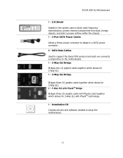
... Table 1. Make sure that the power supply cable and pins are properly aligned with the connector on the motherboard. USB 2.0 Expansion slots CMOS Clear Button 24-pin ATX Power (PW1) PW1 is secure. Firmly plug the power supply cable into the ...
... Table 1. Make sure that the power supply cable and pins are properly aligned with the connector on the motherboard. USB 2.0 Expansion slots CMOS Clear Button 24-pin ATX Power (PW1) PW1 is secure. Firmly plug the power supply cable into the ...

User Guide
Page 24
The current Serial ATA II interface allows up to the motherboard connector. Connection points SATA0 - These connection points support RAID 0, RAID 1, and RAID 10 configurations. TX+ GND...II cables for primary storage devices. Connect the end without the lock to the motherboard. RX- RX+ TX- There are controlled by the South Bridge Chipset. SATA5, are six (6) internal serial... ATA connectors on this motherboard. Connecting Serial ATA Cables The Serial ATA II connector is used to connect the Serial ATA...
The current Serial ATA II interface allows up to the motherboard connector. Connection points SATA0 - These connection points support RAID 0, RAID 1, and RAID 10 configurations. TX+ GND...II cables for primary storage devices. Connect the end without the lock to the motherboard. RX- RX+ TX- There are controlled by the South Bridge Chipset. SATA5, are six (6) internal serial... ATA connectors on this motherboard. Connecting Serial ATA Cables The Serial ATA II connector is used to connect the Serial ATA...