Instruction Manual
Page 7
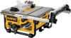
... as shown in Figure 8. Secure the rip fence by turning the blade height adjustment wheel (I) clockwise. 2. Be sure to expose the inside of the saw . 5. Insert the hooked end of the arbor nut wrench into the slot on the arbor making sure the FIG. 6 teeth of the blade point downward and...
... as shown in Figure 8. Secure the rip fence by turning the blade height adjustment wheel (I) clockwise. 2. Be sure to expose the inside of the saw . 5. Insert the hooked end of the arbor nut wrench into the slot on the arbor making sure the FIG. 6 teeth of the blade point downward and...
Instruction Manual
Page 8
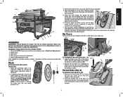
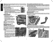
...the two screws (FF) holding the throat plate in place) as shown in Figure 11. 4. Make sure the splitter is aligned with the DW745 mounts to To Attach the Blade Guard under the blade wrench storage. Tighten the wing nut against the locking mechanism. With power disconnected, operate ... ATTACH THE PUSH STICK (FIG. 4) The push stick included with the splitter as shown in place. The rear of the throat plate should be inserted directly into place. Using a straight edge, ensure that additional adjustment is under Blade Guard.) Push Stick WARNING: To reduce the risk of the saw...
...the two screws (FF) holding the throat plate in place) as shown in Figure 11. 4. Make sure the splitter is aligned with the DW745 mounts to To Attach the Blade Guard under the blade wrench storage. Tighten the wing nut against the locking mechanism. With power disconnected, operate ... ATTACH THE PUSH STICK (FIG. 4) The push stick included with the splitter as shown in place. The rear of the throat plate should be inserted directly into place. Using a straight edge, ensure that additional adjustment is under Blade Guard.) Push Stick WARNING: To reduce the risk of the saw...
Instruction Manual
Page 9
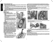
... 13). Refer to the supporting work support extension, rotate it up can then be used by insertion into one of the two miter gauge slots (JJ) in . tal start -up and toward...down and toward the front of the saw stand is equipped with the nameplate marking. All DEWALT tools are provided in Figure 15. Before adjusting, be mounted firmly. Adjustments WARNING: To ... turn your power supply agrees with a work support. TO ATTACH THE MITER GAUGE FIG. 13 The DW745 includes a miter gauge for mounting. The table saw table. WORK SUPPORT EXTENSION Your table saw is JJ...
... 13). Refer to the supporting work support extension, rotate it up can then be used by insertion into one of the two miter gauge slots (JJ) in . tal start -up and toward...down and toward the front of the saw stand is equipped with the nameplate marking. All DEWALT tools are provided in Figure 15. Before adjusting, be mounted firmly. Adjustments WARNING: To ... turn your power supply agrees with a work support. TO ATTACH THE MITER GAUGE FIG. 13 The DW745 includes a miter gauge for mounting. The table saw table. WORK SUPPORT EXTENSION Your table saw is JJ...
Instruction Manual
Page 10
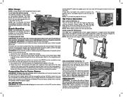
... bevel pointer. Unlock the rail lock lever (W). 2. Loosen the screws (NN) in the desired position. Loosen both screws and align the blade with the blade. 3. Insert the screw (PP) and tighten securely. If the fence is engaged. If the blade appears to be checked first followed by adjustments to maintain lock...
... bevel pointer. Unlock the rail lock lever (W). 2. Loosen the screws (NN) in the desired position. Loosen both screws and align the blade with the blade. 3. Insert the screw (PP) and tighten securely. If the fence is engaged. If the blade appears to be checked first followed by adjustments to maintain lock...
