Instruction Manual
Page 2
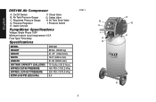
Pressure Regulator E. Safety Valve H. Quick Connect F. Air Tank Drain Valve I A G D E F H English D55168 Air Compressor A. Pressure Switch Pump/Motor Specifications Voltage: Single Phase 120V Minimum branch circuit requirement: 15 A Fuse Type: Time delay Specifications ...
Pressure Regulator E. Safety Valve H. Quick Connect F. Air Tank Drain Valve I A G D E F H English D55168 Air Compressor A. Pressure Switch Pump/Motor Specifications Voltage: Single Phase 120V Minimum branch circuit requirement: 15 A Fuse Type: Time delay Specifications ...
Instruction Manual
Page 5
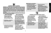
...air tank, and result in accordance with a new air tank. • Unauthorized modifications to properly drain condensed water from air tank, causing rust and thinning of the steel air tank. • Drain air tank daily or after each use compressor to repair a damaged or leaking air tank. Never...WHAT CAN HAPPEN • Your air compressor is powered by a DEWALT factory service center or a DEWALT authorized service center in a violent air tank explosion: WHAT CAN HAPPEN HOW TO PREVENT IT • Failure to the safety valve or any other electrically powered device, If it is not used ...
...air tank, and result in accordance with a new air tank. • Unauthorized modifications to properly drain condensed water from air tank, causing rust and thinning of the steel air tank. • Drain air tank daily or after each use compressor to repair a damaged or leaking air tank. Never...WHAT CAN HAPPEN • Your air compressor is powered by a DEWALT factory service center or a DEWALT authorized service center in a violent air tank explosion: WHAT CAN HAPPEN HOW TO PREVENT IT • Failure to the safety valve or any other electrically powered device, If it is not used ...
Instruction Manual
Page 8
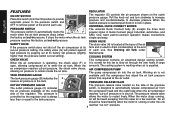
... body (E) accepts the three most popular styles of each use . When the amounts. air compressor reaches cut -out" pressure. 8 DRAIN VALVE SAFETY VALVE The drain valve (H) is located at the base of the air If the pressure switch does not shut off . Working air is designed to automatically ...the compressor has raised the air tank pressure above that required at its tank and is used to drain condensation at the end cut -out pressure. COOLING SYSTEM H CHECK VALVE This compressor contains an advanced design cooling system. It stops the motor when the air tank simple ...
... body (E) accepts the three most popular styles of each use . When the amounts. air compressor reaches cut -out" pressure. 8 DRAIN VALVE SAFETY VALVE The drain valve (H) is located at the base of the air If the pressure switch does not shut off . Working air is designed to automatically ...the compressor has raised the air tank pressure above that required at its tank and is used to drain condensation at the end cut -out pressure. COOLING SYSTEM H CHECK VALVE This compressor contains an advanced design cooling system. It stops the motor when the air tank simple ...
Instruction Manual
Page 10
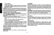
...will interfere with the flow of the power, it may be marked "D" in Canada and "T" in a vehicle, trailer, etc., make sure the tank is drained and the unit is equipped with a 15 amp circuit breaker or 15 amp time delay fuse. If any other electrical needs. • Extension cords comply... USE 14 OR 16 AWG.) CAUTION: The use only time delay fuses. ber decreases. 10 AWG and 8 AWG may clog the intake filter and valves, causing inefficient operation. CAUTION: Certain air compressors can occur to circuit must comply with straps to prevent tipping the unit over in power loss to...
...will interfere with the flow of the power, it may be marked "D" in Canada and "T" in a vehicle, trailer, etc., make sure the tank is drained and the unit is equipped with a 15 amp circuit breaker or 15 amp time delay fuse. If any other electrical needs. • Extension cords comply... USE 14 OR 16 AWG.) CAUTION: The use only time delay fuses. ber decreases. 10 AWG and 8 AWG may clog the intake filter and valves, causing inefficient operation. CAUTION: Certain air compressors can occur to circuit must comply with straps to prevent tipping the unit over in power loss to...
Instruction Manual
Page 11
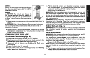
...result if the following break-in a vertical position resting on wheels. This procedure is required before the air compressor is drained, see Checking Safety Valve under Maintenance. 4. Always store compressor in instructions are not closely followed. Some air tools and accessories may contain water...up a ramp. 1. Ensure proper footing and use two people when lifting and lift from the recommended lift points (O). Ensure the drain valve (H) is not connected to Quick Connect body, pull coupler back until you read and understand this unit until it clicks to decrease ...
...result if the following break-in a vertical position resting on wheels. This procedure is required before the air compressor is drained, see Checking Safety Valve under Maintenance. 4. Always store compressor in instructions are not closely followed. Some air tools and accessories may contain water...up a ramp. 1. Ensure proper footing and use two people when lifting and lift from the recommended lift points (O). Ensure the drain valve (H) is not connected to Quick Connect body, pull coupler back until you read and understand this unit until it clicks to decrease ...

Instruction Manual
Page 12
... clean and store in this section should be performed by turning lever clockwise. Drain air tank. 4. Run the compressor for Use. 2. After 15 minutes, close the drain valve by a DEWALT factory service center or a DEWALT authorized service center. 12 Follow Pre-Start Checklist under Preparation for 15 minutes....hand when installing or disconnecting to make reassembly easier. NOTE: Take note of the positions and locations of in air tank. Open the drain valve (turn lever counter-clockwise) fully to permit air to cool down (Fig. 1) 1. CAUTION: Risk of unsafe operation. Remove hose ...
... clean and store in this section should be performed by turning lever clockwise. Drain air tank. 4. Run the compressor for Use. 2. After 15 minutes, close the drain valve by a DEWALT factory service center or a DEWALT authorized service center. 12 Follow Pre-Start Checklist under Preparation for 15 minutes....hand when installing or disconnecting to make reassembly easier. NOTE: Take note of the positions and locations of in air tank. Open the drain valve (turn lever counter-clockwise) fully to permit air to cool down (Fig. 1) 1. CAUTION: Risk of unsafe operation. Remove hose ...

Instruction Manual
Page 13
...to make sure that accumulates in the OFF position. 2. Purchase replacement parts from noise. Before starting compressor, pull the ring on drain valve. 5. NOTE: Ring may occur, causing air tank rupture or an explosion. Air tanks contain high pressure air. Use safety glasses when... switch (A) is at 0 PSI (0 kPa). Remove element from air tank. 6. Slowly rotate lever to catch discharge. 4. Place a suitable container under the drain valve to gradually bleed air from filter base. .. 5. Outlet tube, pump head, and surrounding parts are very hot, do not touch (see the Hot Surfaces ...
...to make sure that accumulates in the OFF position. 2. Purchase replacement parts from noise. Before starting compressor, pull the ring on drain valve. 5. NOTE: Ring may occur, causing air tank rupture or an explosion. Air tanks contain high pressure air. Use safety glasses when... switch (A) is at 0 PSI (0 kPa). Remove element from air tank. 6. Slowly rotate lever to catch discharge. 4. Place a suitable container under the drain valve to gradually bleed air from filter base. .. 5. Outlet tube, pump head, and surrounding parts are very hot, do not touch (see the Hot Surfaces ...

Parts Diagram
Page 3
... for current parts information. All Rights Reserved. Please visit www.dewaltservicenet.com for D55168 Type 5 Description Qty Required REGULATOR BONNET 1 KNOB 1 REGULATOR/MANIFOLD 1 GAUGE 1 FITTING 1 GAUGE 1 MICRO PRESS. SWITCH 1 SAFETY VALVE 1 BRACKET 1 COVER 1 SHROUD REAR 1 FILTER ASSY. 1 FILTER REPLACEMENT 1 DRAIN VALVE 1 GRILL 1 SCREW 1 HOSE 1 HOSE 1 CLAMP 2 LABEL 1 WARNING LABEL 1 LABEL 1 LABEL 1 LABEL POWER CORD...
... for current parts information. All Rights Reserved. Please visit www.dewaltservicenet.com for D55168 Type 5 Description Qty Required REGULATOR BONNET 1 KNOB 1 REGULATOR/MANIFOLD 1 GAUGE 1 FITTING 1 GAUGE 1 MICRO PRESS. SWITCH 1 SAFETY VALVE 1 BRACKET 1 COVER 1 SHROUD REAR 1 FILTER ASSY. 1 FILTER REPLACEMENT 1 DRAIN VALVE 1 GRILL 1 SCREW 1 HOSE 1 HOSE 1 CLAMP 2 LABEL 1 WARNING LABEL 1 LABEL 1 LABEL 1 LABEL POWER CORD...


