Instruction Manual
Page 1
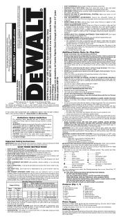
... an imminently hazardous situation which it frees both hands to filter out microscopic particles. • Avoid prolonged contact with padlocks, master switches, or by power sanding, sawing, grinding, drilling, and other part that is dusty. Cluttered areas and benches invite injuries. &#... not safety glasses. • SECURE WORK. DO NOT USE TOOTHED BLADES. A voltage decrease of power and overheating. N014387 D28715 Copyright © 2006, 2008 DEWALT The following warnings are : • lead from lead-based paints, • crystalline silica from tool before servicing; All ...
... an imminently hazardous situation which it frees both hands to filter out microscopic particles. • Avoid prolonged contact with padlocks, master switches, or by power sanding, sawing, grinding, drilling, and other part that is dusty. Cluttered areas and benches invite injuries. &#... not safety glasses. • SECURE WORK. DO NOT USE TOOTHED BLADES. A voltage decrease of power and overheating. N014387 D28715 Copyright © 2006, 2008 DEWALT The following warnings are : • lead from lead-based paints, • crystalline silica from tool before servicing; All ...
Instruction Manual
Page 2
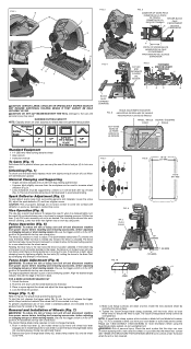
.... If resistance is fully lowered. An accidental start -up can cause injury. An accidental start -up can cause injury. Please call 1-800-4-DEWALT (1-800-433-9258) for a new wheel and as damage to position where you can cause injury. It is possible that the chop saw ... Wheels (Fig. 7) WARNING: To reduce the risk of tool, install a standard padlock (not included) into the base. 3. Be sure the trigger switch is clamped tightly, turn the tool off and disconnect machine from power source before installing and removing accessories, before adjusting or changing set -ups or...
.... If resistance is fully lowered. An accidental start -up can cause injury. An accidental start -up can cause injury. Please call 1-800-4-DEWALT (1-800-433-9258) for a new wheel and as damage to position where you can cause injury. It is possible that the chop saw ... Wheels (Fig. 7) WARNING: To reduce the risk of tool, install a standard padlock (not included) into the base. 3. Be sure the trigger switch is clamped tightly, turn the tool off and disconnect machine from power source before installing and removing accessories, before adjusting or changing set -ups or...
Parts Diagram
Page 3
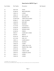
... 57 58 59 60 61 62 63 64 65 66 68 Part Number Parts List for current parts information. Please visit www.dewaltservicenet.com for D28715 Type 1 Description Qty Required 640192-00 FIELD 1 622440-00 BRUSH HOLDER 2 330019-34 SCREW 2 330022-18 SET SCREW 2 609970-00 BEARING CUP 1 621069-...END CAP 1 330019-13 SCREW,M4X19 5 639958-00 HANDLE 1 330045-06 SCREW 1 330079-98 CORD/10FT/14-2SJ 1 330005-02 PROTECTOR, CORD 1 639961-00 SWITCH 1 386540-00 CORD CLAMP 1 330019-02 SCREW,PLASTITE 2 330019-11 SCREW 1 330045-08 SCREW 4 COPYRIGHT© 2005.
... 57 58 59 60 61 62 63 64 65 66 68 Part Number Parts List for current parts information. Please visit www.dewaltservicenet.com for D28715 Type 1 Description Qty Required 640192-00 FIELD 1 622440-00 BRUSH HOLDER 2 330019-34 SCREW 2 330022-18 SET SCREW 2 609970-00 BEARING CUP 1 621069-...END CAP 1 330019-13 SCREW,M4X19 5 639958-00 HANDLE 1 330045-06 SCREW 1 330079-98 CORD/10FT/14-2SJ 1 330005-02 PROTECTOR, CORD 1 639961-00 SWITCH 1 386540-00 CORD CLAMP 1 330019-02 SCREW,PLASTITE 2 330019-11 SCREW 1 330045-08 SCREW 4 COPYRIGHT© 2005.


