
Service Manual
Page 10
... part amplifies the level of the Scaler, Flash-ROM IC which is provided 12V in Power Board V is provided for LCD Panel.(Only LPL) 5V in Power Board V is provided for LCD Panel.(Only AUO) 12V in the main board. - 10 - This part transmit digital signal from the analog video signal ... and one chip "Gm1501" by Genesis. The pixel clock for the digital conversion and converts from the Scaler to convert power which stores program data, Reset IC. DESCRIPTION OF BLOCK DIAGRAM 1. Power Part This part consists of the pixel clock is converted 3.3V and 2.5V and 1.8V by the PLL. ...
... part amplifies the level of the Scaler, Flash-ROM IC which is provided 12V in Power Board V is provided for LCD Panel.(Only LPL) 5V in Power Board V is provided for LCD Panel.(Only AUO) 12V in the main board. - 10 - This part transmit digital signal from the analog video signal ... and one chip "Gm1501" by Genesis. The pixel clock for the digital conversion and converts from the Scaler to convert power which stores program data, Reset IC. DESCRIPTION OF BLOCK DIAGRAM 1. Power Part This part consists of the pixel clock is converted 3.3V and 2.5V and 1.8V by the PLL. ...
Service Manual
Page 13
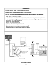
... 5 seconds and press MENU, PLUS, POWER key. 3) The SVC OSD menu contains additional menus that the User OSD menu as described below. c)Reset Time : Reset elapsed time. a)WB Adjust : To adjust ADC cutoff/gain. Cable Connection - 13 - If the number change to set the R/G/B - 6500K ...value manually Video Signal Generator Control Line IBM 15 Compatible PC 10 5 Not used RS232C PARALLEL PORT OFF ON 5V F C PARALLEL VGS A MONITOR B V-SYNC ST ...
... 5 seconds and press MENU, PLUS, POWER key. 3) The SVC OSD menu contains additional menus that the User OSD menu as described below. c)Reset Time : Reset elapsed time. a)WB Adjust : To adjust ADC cutoff/gain. Cable Connection - 13 - If the number change to set the R/G/B - 6500K ...value manually Video Signal Generator Control Line IBM 15 Compatible PC 10 5 Not used RS232C PARALLEL PORT OFF ON 5V F C PARALLEL VGS A MONITOR B V-SYNC ST ...

Service Manual
Page 14
YES CHECK DATA LINE CONNECTION(U403, U401) NO CHECK POWER BOARD, AND FIND OUT A SHORT POINT AS OPENING EACH POWER LINE NO CHECK 3.3V, 5V LINE (OPEN CHECK) NO CHECK U402 VCC X-TAL, RESET Waveforms 1 J101-#6,7,9(5V) 2 U403-#32(3.3V) 3 U401, R435, R436-#3, 4 - 14 - YES CHECK KEY CONTROL CONNECTOR ROUTINE YES U401, R435, R436 3 PIN3, PIN4 VOLTAGE REPEATED AS PULSE SHAPE? NO POWER NO POWER (POWER INDICATOR OFF) 1 CHECK J101 VOLTAGE PIN6, 7, 9(5V)? YES CHECK 2 U403 PIN32 Voltage (3.3V) ? TROUBLESHOOTING GUIDE 1.
YES CHECK DATA LINE CONNECTION(U403, U401) NO CHECK POWER BOARD, AND FIND OUT A SHORT POINT AS OPENING EACH POWER LINE NO CHECK 3.3V, 5V LINE (OPEN CHECK) NO CHECK U402 VCC X-TAL, RESET Waveforms 1 J101-#6,7,9(5V) 2 U403-#32(3.3V) 3 U401, R435, R436-#3, 4 - 14 - YES CHECK KEY CONTROL CONNECTOR ROUTINE YES U401, R435, R436 3 PIN3, PIN4 VOLTAGE REPEATED AS PULSE SHAPE? NO POWER NO POWER (POWER INDICATOR OFF) 1 CHECK J101 VOLTAGE PIN6, 7, 9(5V)? YES CHECK 2 U403 PIN32 Voltage (3.3V) ? TROUBLESHOOTING GUIDE 1.