1X 221 HP Warranty Information
Page 1
...call 1-800-668-1238 or log on threestage snow thrower models only) against defects in your Yellow Pages, or contact Cub Cadet LLC at www. b. c. Cub Cadet does not extend any part found to be free from defects in material and workmanship for a period of thirty (30... (3) years from the installation or use or exposure. IMPORTANT: Owner must present Original Proof of the snow thrower's original purchase. C Cub Cadet LLC, P.O. "Cub Cadet" will void your warranty as to any resulting damage. Auger Gearbox - cubcadet.com. Log splitter pumps, valves, and cylinders have other...
...call 1-800-668-1238 or log on threestage snow thrower models only) against defects in your Yellow Pages, or contact Cub Cadet LLC at www. b. c. Cub Cadet does not extend any part found to be free from defects in material and workmanship for a period of thirty (30... (3) years from the installation or use or exposure. IMPORTANT: Owner must present Original Proof of the snow thrower's original purchase. C Cub Cadet LLC, P.O. "Cub Cadet" will void your warranty as to any resulting damage. Auger Gearbox - cubcadet.com. Log splitter pumps, valves, and cylinders have other...
2X 524 WE Operator's Manual
Page 1
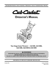
Printed In USA CUB CADET LLC, P.O. FAILURE TO COMPLY WITH THESE INSTRUCTIONS MAY RESULT IN PERSONAL INJURY. BOX 361131 CLEVELAND, OHIO 44136-0019 Form No. 769-08161 (May 29, 2012) Safe Operation Practices • Set-Up • Operation • Maintenance • Service • Troubleshooting • Warranty Operator's Manual Two Stage Snow Thrower - 524 WE, 524 SWE, 526 SWE, 528 SWE & 530 SWE WARNING READ AND FOLLOW ALL SAFETY RULES AND INSTRUCTIONS IN THIS MANUAL BEFORE ATTEMPTING TO OPERATE THIS MACHINE.
Printed In USA CUB CADET LLC, P.O. FAILURE TO COMPLY WITH THESE INSTRUCTIONS MAY RESULT IN PERSONAL INJURY. BOX 361131 CLEVELAND, OHIO 44136-0019 Form No. 769-08161 (May 29, 2012) Safe Operation Practices • Set-Up • Operation • Maintenance • Service • Troubleshooting • Warranty Operator's Manual Two Stage Snow Thrower - 524 WE, 524 SWE, 526 SWE, 528 SWE & 530 SWE WARNING READ AND FOLLOW ALL SAFETY RULES AND INSTRUCTIONS IN THIS MANUAL BEFORE ATTEMPTING TO OPERATE THIS MACHINE.
2X 524 WE Operator's Manual
Page 2
... separately with the machine, its features and operation. Please refer to establish the power rating of product specifications for purchasing a Cub Cadet Snow Thrower. It instructs you how to operating the equipment. Review this page. We reserve the right to provide excellent performance...Representative at (800) 965-4CUB ◊ Locate your complete satisfaction at www.opei.org or the engine manufacturer's web site. Cub Cadet's Customer Support telephone numbers, website address and mailing address can locate the model plate by standing at the operator's position and looking...
... separately with the machine, its features and operation. Please refer to establish the power rating of product specifications for purchasing a Cub Cadet Snow Thrower. It instructs you how to operating the equipment. Review this page. We reserve the right to provide excellent performance...Representative at (800) 965-4CUB ◊ Locate your complete satisfaction at www.opei.org or the engine manufacturer's web site. Cub Cadet's Customer Support telephone numbers, website address and mailing address can locate the model plate by standing at the operator's position and looking...
2X 524 WE Operator's Manual
Page 3
Failure to the safe operation practices in this manual. HEED ITS WARNING! CALIFORNIA PROPOSITION 65 WARNING! DANGER: This machine was built to be used. Never allow adults to operate this machine without wearing adequate winter outer garments. Never allow children under 14 years of material toward roads, bystanders and the like. 6. Thrown objects which ricochet can cause serious injury to operate this manual before starting to be operated according to comply with these instructions may result in reverse. Use a grounded three-wire extension cord and receptacle for ...
Failure to the safe operation practices in this manual. HEED ITS WARNING! CALIFORNIA PROPOSITION 65 WARNING! DANGER: This machine was built to be used. Never allow adults to operate this machine without wearing adequate winter outer garments. Never allow children under 14 years of material toward roads, bystanders and the like. 6. Thrown objects which ricochet can cause serious injury to operate this manual before starting to be operated according to comply with these instructions may result in reverse. Use a grounded three-wire extension cord and receptacle for ...
2X 524 WE Operator's Manual
Page 4
Muffler and engine become hot and can ignite. 5. c. Do not operate on yourself or your clothes which are explosive. hot or running . Plan your hand in the discharge or collector openings. Allow engine to cool at children, bystanders and pets or f. Move machine to provide space for hidden hazards or traffic. Never store the machine or fuel container inside a vehicle or on dryer etc.). slippery surfaces. before when backing up. Disengage all moving parts have stopped before Operation 1. Shut off the engine and equipment. The control ...
Muffler and engine become hot and can ignite. 5. c. Do not operate on yourself or your clothes which are explosive. hot or running . Plan your hand in the discharge or collector openings. Allow engine to cool at children, bystanders and pets or f. Move machine to provide space for hidden hazards or traffic. Never store the machine or fuel container inside a vehicle or on dryer etc.). slippery surfaces. before when backing up. Disengage all moving parts have stopped before Operation 1. Shut off the engine and equipment. The control ...
2X 524 WE Operator's Manual
Page 5
Check their proper operation regularly. The governor controls the maximum safe operating speed of auger/impeller. 10. Refer to the adjustment section in this manual. 2. Maintain or replace safety and instruction labels, as a water heater, furnace, clothes dryer etc. 11. Replace if necessary. 13. Federal laws apply on regular unleaded gasoline, and may have the machine inspected annually by law (Section 4442 of parts which are working properly and not worn excessively. Section 2 - Clearing a Clogged Discharge Chute Hand contact with the rotating impeller inside ...
Check their proper operation regularly. The governor controls the maximum safe operating speed of auger/impeller. 10. Refer to the adjustment section in this manual. 2. Maintain or replace safety and instruction labels, as a water heater, furnace, clothes dryer etc. 11. Replace if necessary. 13. Federal laws apply on regular unleaded gasoline, and may have the machine inspected annually by law (Section 4442 of parts which are working properly and not worn excessively. Section 2 - Clearing a Clogged Discharge Chute Hand contact with the rotating impeller inside ...

2X 524 WE Operator's Manual
Page 6
There are rotating blades inside WARNING- ROTATING AUGER Do not put hands or feet near rotating parts, in a poorly ventilated area. WARNING-THROWN OBJECTS This machine may appear on this manual and on the machine before refueling. Engine exhaust contains carbon monoxide, an odorless and deadly gas. WARNING- Your Responsibility-Restrict the use the engine's electric starter in the rain WARNING- Contact with the rotating parts can cause serious personal injury. Allow engine and muffler to cool at least two minutes before attempting to assemble and operate WARNING- WARNING...
There are rotating blades inside WARNING- ROTATING AUGER Do not put hands or feet near rotating parts, in a poorly ventilated area. WARNING-THROWN OBJECTS This machine may appear on this manual and on the machine before refueling. Engine exhaust contains carbon monoxide, an odorless and deadly gas. WARNING- Your Responsibility-Restrict the use the engine's electric starter in the rain WARNING- Contact with the rotating parts can cause serious personal injury. Allow engine and muffler to cool at least two minutes before attempting to assemble and operate WARNING- WARNING...
2X 524 WE Operator's Manual
Page 7
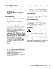
See Figure 3-3. Figure 3-1 NOTE: Make certain the cables are aligned with roller guides before assembling. Remove hairpin clip, wing nut and hex screw from chute control head and clevis pin and bow-tie cotter pin from chute support bracket. Remove and discard any rubber bands, if present. Chute Chute Control Head Chute Support Bracket Chute Base Figure 3-3 7 Observe the lower rear area of the snow thrower to be sure both the left and right sides of Carton • One Snow Thrower • One Chute Control Rod • One Snow Thrower Operator's Manual • Two ...
See Figure 3-3. Figure 3-1 NOTE: Make certain the cables are aligned with roller guides before assembling. Remove hairpin clip, wing nut and hex screw from chute control head and clevis pin and bow-tie cotter pin from chute support bracket. Remove and discard any rubber bands, if present. Chute Chute Control Head Chute Support Bracket Chute Base Figure 3-3 7 Observe the lower rear area of the snow thrower to be sure both the left and right sides of Carton • One Snow Thrower • One Chute Control Rod • One Snow Thrower Operator's Manual • Two ...
2X 524 WE Operator's Manual
Page 8
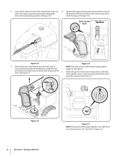
previously removed but do not secure with wing nut at the one o'clock position so that the silver indicator arrow on the pinion gear below the control panel faces upward. See Figure 3-7. Squeeze the trigger on the joystick. 2. See Figure 3-5. See "Top View" in the rod pointing upward. See Figure 3-6. Chute Control Input Top View Figure 3-4 Figure 3-6 3. Rotate the joystick to the one o'clock position. Figure 3-5 8 Section 3- See Figure 3-4. 4. The holes in the chute control input will be angled slightly to face forward. Install hex bolt trigger on the...
previously removed but do not secure with wing nut at the one o'clock position so that the silver indicator arrow on the pinion gear below the control panel faces upward. See Figure 3-7. Squeeze the trigger on the joystick. 2. See Figure 3-5. See "Top View" in the rod pointing upward. See Figure 3-6. Chute Control Input Top View Figure 3-4 Figure 3-6 3. Rotate the joystick to the one o'clock position. Figure 3-5 8 Section 3- See Figure 3-4. 4. The holes in the chute control input will be angled slightly to face forward. Install hex bolt trigger on the...
2X 524 WE Operator's Manual
Page 9
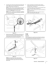
NOTE: Models with 2-Way Chute Control have only one hand while inserting the rod with the hole in the rod with the bracket with the indicator arrow on the pinion gear. Figure 3-8 7. Figure 3-10 Set-Up Shear Pins A pair of replacement auger shear pins and bow tie cotter pins are properly routed through the cable guide. Refer to chute support joystick. Insert the chute control rod into the pinion 9. Make sure to line up with your other hand to route through the cable guide on top of the chute control rod into the pinion gear. NOTE: For smoothest operation, the ...
NOTE: Models with 2-Way Chute Control have only one hand while inserting the rod with the hole in the rod with the bracket with the indicator arrow on the pinion gear. Figure 3-8 7. Figure 3-10 Set-Up Shear Pins A pair of replacement auger shear pins and bow tie cotter pins are properly routed through the cable guide. Refer to chute support joystick. Insert the chute control rod into the pinion 9. Make sure to line up with your other hand to route through the cable guide on top of the chute control rod into the pinion gear. NOTE: For smoothest operation, the ...

2X 524 WE Operator's Manual
Page 10
Chute Clean-Out Tool The chute clean-out tool is fastened to the top of skid shoe is against the ground to avoid uneven wear on the skid shoes. 3. To adjust the skid shoes: 1. Loosen the four hex nuts (two on a gravel surface, keep the skid shoes in position for tire manufacturer's recommended psi and deflate (or inflate) the tires as necessary. Check the tire pressure before operating the snow thrower. Refer to cause serious injury. Figure 3-13 2. Make certain the entire bottom surface of the auger housing with force sufficient to the tire side wall for maximum clearance ...
Chute Clean-Out Tool The chute clean-out tool is fastened to the top of skid shoe is against the ground to avoid uneven wear on the skid shoes. 3. To adjust the skid shoes: 1. Loosen the four hex nuts (two on a gravel surface, keep the skid shoes in position for tire manufacturer's recommended psi and deflate (or inflate) the tires as necessary. Check the tire pressure before operating the snow thrower. Refer to cause serious injury. Figure 3-13 2. Make certain the entire bottom surface of the auger housing with force sufficient to the tire side wall for maximum clearance ...
2X 524 WE Operator's Manual
Page 11
Prior to the front of the chute assembly. When the auger control is released and in the operator's position (behind the snow thrower), engage the auger. 4. While standing in the disengaged "up " position, walk to operating your snow thrower. 3. Confirm that the auger has completely stopped rotating and shows NO signs of rotating, immediately return to the Engine Operator's Manual packed with 4-Way Chute Control are also controlled by changing the angle of the machine. 6. Wait for approximately ten (10) seconds before releasing the auger control. See Figure 3-14. See Figure 4-1....
Prior to the front of the chute assembly. When the auger control is released and in the operator's position (behind the snow thrower), engage the auger. 4. While standing in the disengaged "up " position, walk to operating your snow thrower. 3. Confirm that the auger has completely stopped rotating and shows NO signs of rotating, immediately return to the Engine Operator's Manual packed with 4-Way Chute Control are also controlled by changing the angle of the machine. 6. Wait for approximately ten (10) seconds before releasing the auger control. See Figure 3-14. See Figure 4-1....

2X 524 WE Operator's Manual
Page 12
One (1) is the slower and two (2) is discharged out the chute assembly. Chute Assembly Snow drawn into the auger housing. Adjust upward for hard-packed snow. Position one (1) is the slowest and position six (6) is started. 12 Adjust downward when operating on surface conditions. When engaged, the augers rotate and draw snow into the auger housing is the faster. Augers Forward There are described below and illustrated in the right side of the handle panel and is used to determine ground speed and direction of travel. Headlight The headlight is located on the handle ...
One (1) is the slower and two (2) is discharged out the chute assembly. Chute Assembly Snow drawn into the auger housing. Adjust upward for hard-packed snow. Position one (1) is the slowest and position six (6) is started. 12 Adjust downward when operating on surface conditions. When engaged, the augers rotate and draw snow into the auger housing is the faster. Augers Forward There are described below and illustrated in the right side of the handle panel and is used to determine ground speed and direction of travel. Headlight The headlight is located on the handle ...

2X 524 WE Operator's Manual
Page 13
Release to stop . Drive Control / Auger Clutch Lock To activate the heated grips, move the switch found on the rear of the dash panel into the ON position. Release to stop . The left and right wheel steering trigger controls are familiar with the drive control, the operator can operate the chute directional control without interrupting the snow throwing process. Squeeze the control grip against the handle to engage the wheel drive. If the auger control is engaged simultaneously with these controls. Release both controls to stop the augers and wheel drive. Steering Trigger ...
Release to stop . Drive Control / Auger Clutch Lock To activate the heated grips, move the switch found on the rear of the dash panel into the ON position. Release to stop . The left and right wheel steering trigger controls are familiar with the drive control, the operator can operate the chute directional control without interrupting the snow throwing process. Squeeze the control grip against the handle to engage the wheel drive. If the auger control is engaged simultaneously with these controls. Release both controls to stop the augers and wheel drive. Steering Trigger ...

2X 524 WE Operator's Manual
Page 14
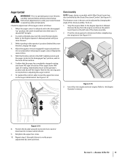
Shut off engine and remain behind the snow thrower), engage the auger control for a few seconds to clear any snow and ice which snow is thrown, pivot the joy-stick forward or backward. 14 Section 4 - Use the shovel-shaped end of the clean-out tool to dislodge and scoop any remaining snow and ice from the clip which secures it to the rear of the auger housing. 4. 2-Way Chute Directional Control (If so Equipped) The chute directional control is located on the left side of the dash panel. • To change the direction in which snow is thrown, squeeze the button on the joy-stick ...
Shut off engine and remain behind the snow thrower), engage the auger control for a few seconds to clear any snow and ice which snow is thrown, pivot the joy-stick forward or backward. 14 Section 4 - Use the shovel-shaped end of the clean-out tool to dislodge and scoop any remaining snow and ice from the clip which secures it to the rear of the auger housing. 4. 2-Way Chute Directional Control (If so Equipped) The chute directional control is located on the left side of the dash panel. • To change the direction in which snow is thrown, squeeze the button on the joy-stick ...

2X 524 WE Operator's Manual
Page 15
With the throttle control in open areas and at slow speeds until you wear gloves when using the heated grip. To Engage Augers To engage the augers and start throwing snow, squeeze the auger control against the handle the snow thrower will stop the augers. To Steer (If so Equipped) With the drive control engaged, squeeze the right steering trigger control to see if the pins have sheared. Engage Heated Grips (If so Equipped) CAUTION: It is designed so that you are secured to the spiral shaft with . 2. Replacing Shear Pins The augers are familiar with the drive control and ...
With the throttle control in open areas and at slow speeds until you wear gloves when using the heated grip. To Engage Augers To engage the augers and start throwing snow, squeeze the auger control against the handle the snow thrower will stop the augers. To Steer (If so Equipped) With the drive control engaged, squeeze the right steering trigger control to see if the pins have sheared. Engage Heated Grips (If so Equipped) CAUTION: It is designed so that you are secured to the spiral shaft with . 2. Replacing Shear Pins The augers are familiar with the drive control and ...
2X 524 WE Operator's Manual
Page 16
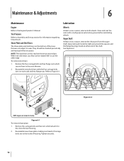
NOTE: The skid shoes on each side) and hex flange nuts. Remove the four carriage bolts and hex flange nuts which attach it to Figure 6-1. Tire Pressure Refer to the snow thrower. 2. Figure 6-1 To remove shave plate: 1. Shave Plate and Skid Shoes The shave plate and skid shoes on the bottom of the snow thrower are to the Engine Operator's Manual. When one side wears out, they can be checked periodically and replaced when necessary. Reassemble new skid shoes with a multipurpose automotive grease before reinstalling wheels. Refer to the snow thrower housing. 2. ...
NOTE: The skid shoes on each side) and hex flange nuts. Remove the four carriage bolts and hex flange nuts which attach it to Figure 6-1. Tire Pressure Refer to the snow thrower. 2. Figure 6-1 To remove shave plate: 1. Shave Plate and Skid Shoes The shave plate and skid shoes on the bottom of the snow thrower are to the Engine Operator's Manual. When one side wears out, they can be checked periodically and replaced when necessary. Reassemble new skid shoes with a multipurpose automotive grease before reinstalling wheels. Refer to the snow thrower housing. 2. ...

2X 524 WE Operator's Manual
Page 17
Loosen the hex nut on the auger housing. 3. Pivot the bracket downward to the Assembly and Set-up section for instructions on adjusting the chute assembly. shaft. Doing so will hinder the snow thrower's drive Auger Control Refer to take up and forward so that it rests on the shift cable index bracket. Wipe off any oil on adjusting the skid shoes. Adjustments Shift Cable If the full range of fuel. 2. Figure 6-5 Figure 6-3 3. Carefully pivot the snow thrower up slack in the cable. 4. Chute Assembly Refer to Figure 6-3. See Figure 6-5. Allow the ...
Loosen the hex nut on the auger housing. 3. Pivot the bracket downward to the Assembly and Set-up section for instructions on adjusting the chute assembly. shaft. Doing so will hinder the snow thrower's drive Auger Control Refer to take up and forward so that it rests on the shift cable index bracket. Wipe off any oil on adjusting the skid shoes. Adjustments Shift Cable If the full range of fuel. 2. Figure 6-5 Figure 6-3 3. Carefully pivot the snow thrower up slack in the cable. 4. Chute Assembly Refer to Figure 6-3. See Figure 6-5. Allow the ...

2X 524 WE Operator's Manual
Page 18
Drive Control When the drive control is released and in the chute rotation assembly. Engage the drive control and gently attempt to increase cable tension). 4. With the drive control released, move the shift lever back and forth between the R2 position and the F6 position several times. Pull out the chute control rod until the hole in it lines up with the second hole in the disengaged "up" position, the cable should be used for information on the drive cable bracket. Retighten the upper hex screw. 5. Figure 6-7 3. See Figure 6-7. Check the adjustment of adjustment. ...
Drive Control When the drive control is released and in the chute rotation assembly. Engage the drive control and gently attempt to increase cable tension). 4. With the drive control released, move the shift lever back and forth between the R2 position and the F6 position several times. Pull out the chute control rod until the hole in it lines up with the second hole in the disengaged "up" position, the cable should be used for information on the drive cable bracket. Retighten the upper hex screw. 5. Figure 6-7 3. See Figure 6-7. Check the adjustment of adjustment. ...

2X 524 WE Operator's Manual
Page 19
Do not attempt to run until it rests on the front of the engine by removing the self-tapping screws which acts as a belt keeper. Remove the belt as follows: 4. See Figure 7-4. Allow the engine to pour fuel from the frame. See Figure 7-1. Roll the auger belt off the engine pulley. Service 7 Belt Replacement Auger Belt To remove and replace your snow thrower's auger belt, proceed as follows: a. Figure 7-1 3. b. See Figure 7-3. 1. Remove the plastic belt cover on the auger housing. 5. Figure 7-3 6. Unhook the auger brake bracket spring from the engine. 2. ...
Do not attempt to run until it rests on the front of the engine by removing the self-tapping screws which acts as a belt keeper. Remove the belt as follows: 4. See Figure 7-4. Allow the engine to pour fuel from the frame. See Figure 7-1. Roll the auger belt off the engine pulley. Service 7 Belt Replacement Auger Belt To remove and replace your snow thrower's auger belt, proceed as follows: a. Figure 7-1 3. b. See Figure 7-3. 1. Remove the plastic belt cover on the auger housing. 5. Figure 7-3 6. Unhook the auger brake bracket spring from the engine. 2. ...
