Owners Manual
Page 2
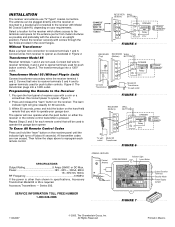
...Model 95 outlet Transformer FIGURE 6 OPENING RECEIVER Connect Antenna OPEN RECEIVER Indicator Light Learn Button C P2 M HIGH NORM 24V 12V Output Duration Terminals Security Mode Power Supply Jumper FIGURE 7 114A3097 © 2005, The Chamberlain Group, Inc. Connect bell wire to receiver terminals 3 and 4 and to ...control. INSTALLATION The receiver and antenna use TV Type F coaxial connectors. Select a location for the receiver which allows access to the terminals and space for the antenna (as far from receiver to opener terminals used . Fasten the receiver securely with the ...
...Model 95 outlet Transformer FIGURE 6 OPENING RECEIVER Connect Antenna OPEN RECEIVER Indicator Light Learn Button C P2 M HIGH NORM 24V 12V Output Duration Terminals Security Mode Power Supply Jumper FIGURE 7 114A3097 © 2005, The Chamberlain Group, Inc. Connect bell wire to receiver terminals 3 and 4 and to ...control. INSTALLATION The receiver and antenna use TV Type F coaxial connectors. Select a location for the receiver which allows access to the terminals and space for the antenna (as far from receiver to opener terminals used . Fasten the receiver securely with the ...